

Two options are available to add pads to a footprint:
- Insert Pad is used to insert a Component Pad into a PCB Footprint, and to insert a Pad into a PCB Documentation Symbol. These are numbered pads which are different to free pads which can be added using the Free Pads option.
- Insert SMD Pad is used to insert a Surface Mounted Component Pad into a PCB Footprint.
Shortcuts
Default Keys: None
Default Menu: Insert
Command: Insert Pad
Default Keys: None
Default Menu: Insert
Command: Insert SMD Pad
How To Insert A Pad
-
Select the Insert Pad or Insert SMD Pad icon from the Insert menu, select Pad or SMD Pad.
-
A pad will appear in the footprint, moving at the end of the cursor. If another pad was selected prior to entering the option, then the new pad’s style, layer and pin number position will be copied from it. Otherwise, the pad’s details and it’s names style will be as defined in Pad Defaults.
The pad will be allocated the next free pin number not already used in the footprint.
-
Right click to use the shortcut menu as follows:
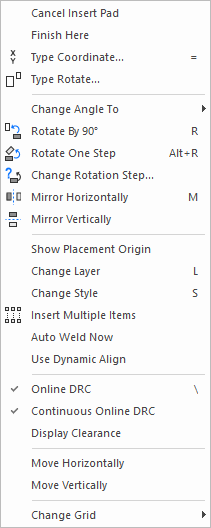
-
Move the pad to the correct position and left click to release it. Another pad using the same style and layer, but with the next pin number will appear for you to place next.
-
When all pads have been added, press the Escape key to exit the insert pad mode. The pad currently being moved will be deleted.
After adding all the pads the pin numbers may be dragged into more convenient positions. Use the Renumber Pins option to set the correct pin order on the footprint.
Related Topics
Change Grid | Change Layer | Change Style | Display Clearance | Insert Multiple Items | Online DRC | Pad Defaults | Renumber Pins | Technology