RF Design in Pulsonix
RF Circuit Support in Pulsonix
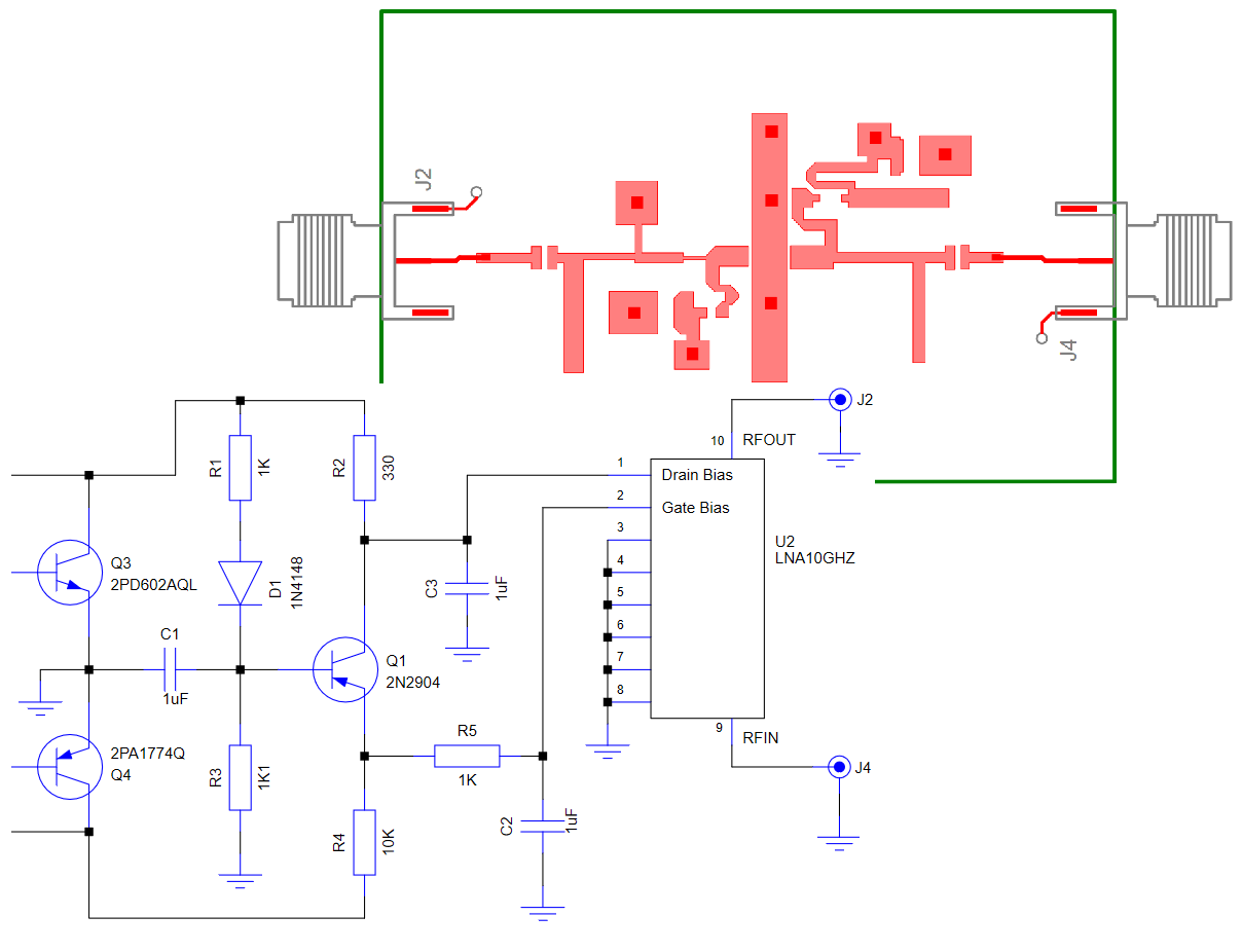
Use a collection of powerful tools within Pulsonix to create your RF designs
The Pulsonix design tool supports RF (radio frequency) design through flexible design features integrated within the Schematic and PCB applications.
With the Pulsonix RF option, you can create RF specific features such as chamfered corners (where the inner corner is 90-degrees and the outer corner is 45-degrees), curved corners, flat ended tracks, and track back-off to avoid over-shoot.
Additional features include Gerber, DXF, IDF and STEP Import to generate complex shapes that have been calculated in external applications, such as Ansys, CST Microwave Studio, Simberian and RFSim99 from AD5GG. Many other products are also supported.
Powerful shape facilities within Pulsonix means complex shapes can be generated with ease and accuracy, these can be added to designs and libraries for completeness.
Library Components
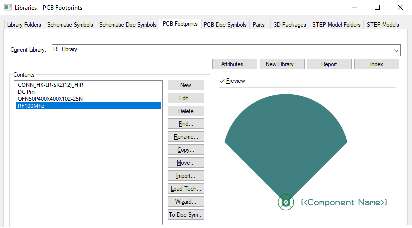
Components in Pulsonix can be supported for RF design using standard tools within the product. Where standard RF shapes are required in the PCB footprint, they can be created by hand using facilities such as powerful Construction Lines and shape addition. Where shapes or components have been created externally, these can be imported using one of the Pulsonix Gerber import filters and native .plx, and the footprints saved for use.
Schematic Capture
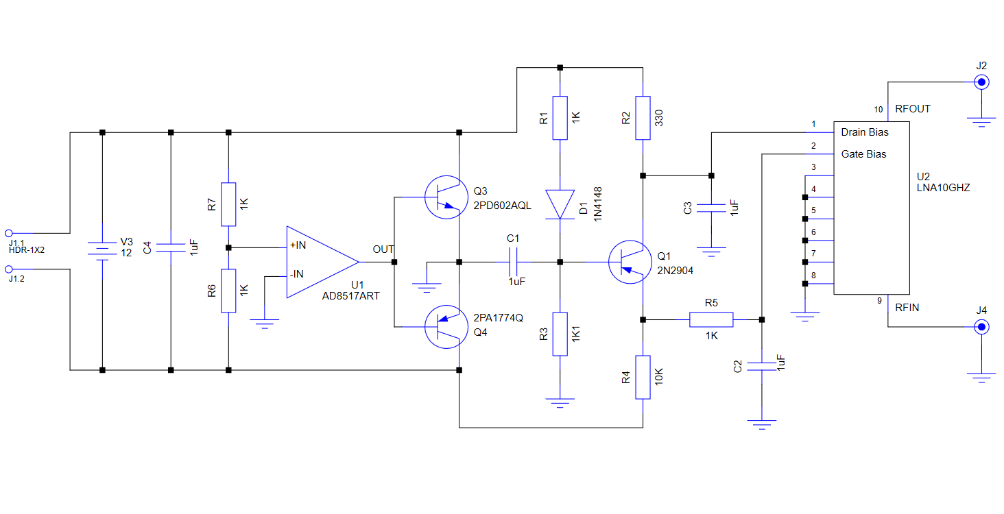
Create clear and concise schematic drawings in this easy-to-use design environment. A fully coherent schematic will mean front to back design integrity at all stages of the design. The Pulsonix schematic will generate the PCB data, it can also be used to create the Spice simulation netlist using the same component libraries, all within the one integrated application.
Spice Simulation
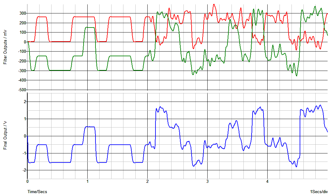
Generate Spice netlists from the Pulsonix schematic editor to your Spice simulator of choice. Pulsonix supports industry Spice application such as LTSpice, PSpice, SiMetrix, Micro-Cap etc. An integrated interface allows you to design the Spice type and also run the simulator engine from within Pulsonix.
Layers and Layer Stacks
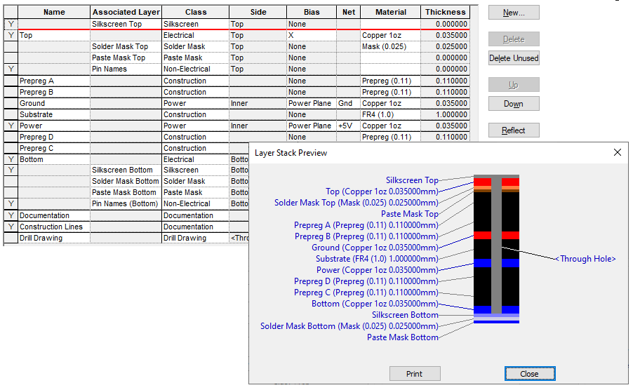
Layers with RF specific materials can easily be added to the Pulsonix PCB design. If layer stacks are created, calculated and verified externally to Pulsonix, these can then be imported into your PCB design using the IPC-2581 import option.
Board Materials
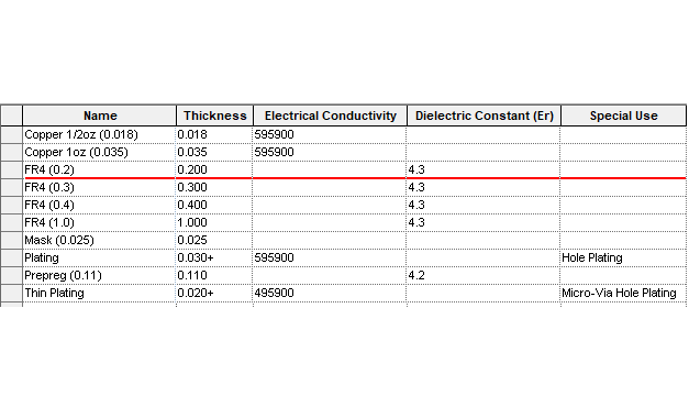
Pulsonix supports PCB and RF design materials along with their thickness, Electrical Conductivity and Dielectric Constant. When used on layers, these values are exported to the required formats for other systems, such as in the IPC-2581. Construction materials, foils and structures can be easily created and used on your layers.
Complex Shapes and Shielding
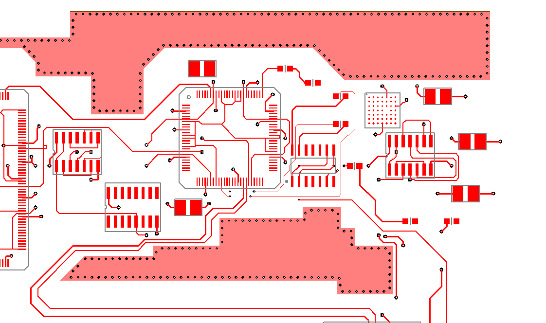
Create complex shapes with Pulsonix PCB for RF for amplifiers, antennas, attenuators, passive and active filters, striplines and waveguides using the powerful tools provided. Add vias to copper shapes for stapling and shielding. Vias can also be added around tracks for shielding.
Track Impedance
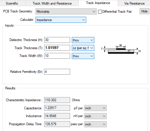
Built-in design calculators are available to help calculate the track impedance during design based on the given track width and copper thickness. This calculator can also be used to calculate track thickness based on a required track impedance.
Integration With External Verification Tools
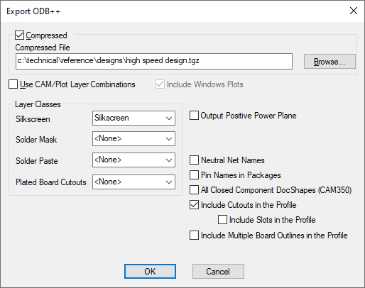
Pulsonix supports interfaces to many external tools for PCB simulation, including impedance matching, crosstalk analysis as well as Spice simulation. Pulsonix supports export formats, such as OBD++, IPC-2581, STEP and Spice. Where your process requires specialist RF design tools, Pulsonix can import data created as Gerber or DXF to ensure accuracy is maintained.
Manufacturing Outputs
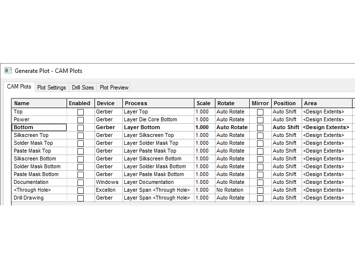
Write industry formats from Pulsonix to manufacture your RF designs using Gerber, ODB++, IPC-2581, NC-Drill, BOM, pick & place and assembly outputs. All exports are fully user customisable and tailored to your requirements.

