
Interactive 3D Design
Interactive 3D Design
Place Components and Enclosures in 3D with real-time online DRC for clash detection
Component Placement
Select and move Components in the 3D environment with changes automatically back annotated to the PCB design. Fine tuning placement and detecting clashes in 3D with enclosures avoids costly manufacturing errors.
Working with Enclosures
Enclosures can be added to the design, viewed and moved within the 3D environment. The Colour and Transparency setting for enclosures can be defined enabling clearer differentiation between housings and Components.
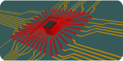
Online Clash Detection
Clash Rules definition and detection provides real time feedback for enclosures and Components. Enclosure spacings defined in the PCB are used in 3D with all clashes detected and highlighted visually, helping eliminate costly errors.
Flexi-Rigid Technology
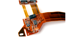
True Flexi-rigid support is available using the features within the Advanced Technology package; Multi-spanned Layer Areas, Board Outlines, Board Cutouts and Layer Spanned Components. Using these powerful options, Board outlines can be created to span 'internal' flexi layers that are still exposed externally.
Layer Spanned Components
Adding Components to layer spans allow them to be exposed. Components on inner flexi layers can be achieved but with true 'side' and layer characteristics available within their Properties. This means accurate assembly reports, manufacturing plots and precise build details can be exported for accurate manufacturing.
Advanced Layer Spans
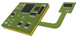
Advanced layer span definitions enable you to create the regular board outline plus the board outline required for an inner flexi-layer which may extend outside of the normal board boundaries.
Reality and Visualisation
With a powerful engine featuring anti-alias rendering, realistic lighting and a gradient background, the 3D environment provides you with realistic visualisation of your PCB.
ECAD to MCAD Support
Bridge your ECAD-MCAD work flow and design environments with support for STEP, DXF and IDF. All bi-directional interfaces can utilise critical board outlines and Component placement.
Technology Based Rules
All rules created for Enclosure Clash spacings and Component Placement grids are dynamically passed through from the PCB environment into 3D ensuring rules are adhered to at all times.
Discover why thousands of companies around the world choose Pulsonix
"The capability of Pulsonix and the supportive team at Westdev have helped us make this important transition and to move forward."
Mark Wilkinson - Copernica