
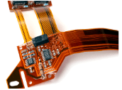
Flexi-Board Technology
Leading Edge Technology for today's modern designs
Essential functionality to support Flexi-rigid board designs
Flexi-Rigid Design Support
Flexi-Board Technology
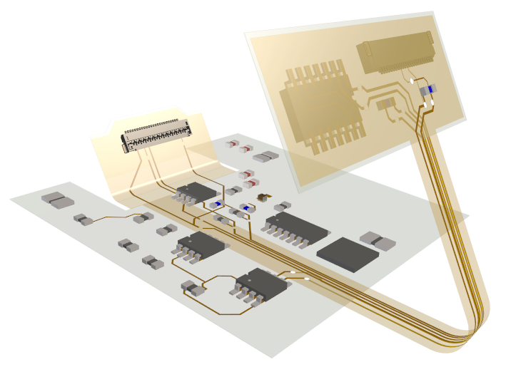
True Flexi-rigid support is available for multi-layer spanned areas, layer
spanned components, bend region definition along with animated bend visualisation.
Easily and quickly define Layer spans, stack-ups, board stiffeners, cutouts and
bend regions to create your flexi design.
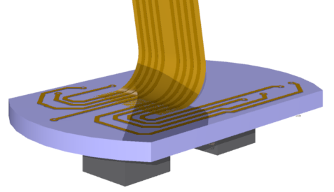
Layer Spanned Components
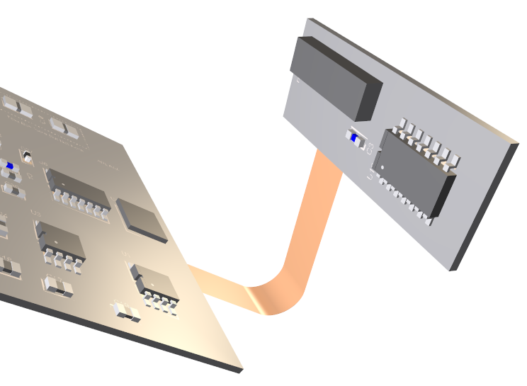
Adding Components to layer spans allow them to be exposed. Components on inner flexi layers can be achieved but with true 'side' and layer characteristics available within their Properties. This means accurate assembly reports, manufacturing plots and precise build details can be exported for accurate manufacturing.
Flexi Board Animation
Visualise your flexi board designs using animated 3D bending in the 3D viewer
where bends and curves can be seen moving in real time using realistic animation.
Bend regions enable direction and angle to be defined as well as the radius of the
bend. Animation also allows multiple boards to be ‘stacked’ and clashes highlighted.
Flexi Bend Regions
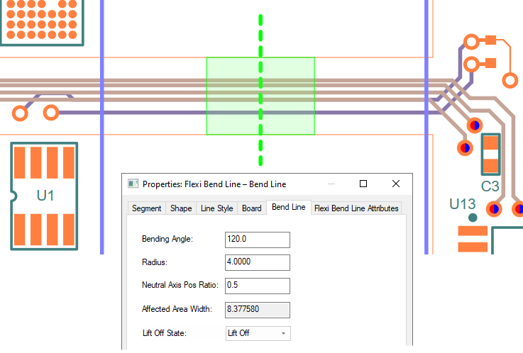
Bend regions are created so that the flexi option knows how the bending should be performed. It contains key parameters to define the size and direction/angle of bend as well as providing a Component and Via Keepout area used for DRC checking. A ‘Lift-off’ state and Neutral Bending Axis add advanced parameteres.
Bend Region Lift-off State
A ‘Lift-off’ state can be applied to Flexi bend regions. This means the flexi portion of the board can start within an existing boundary and not exit through the ‘edge’ of the board. The bend transforms from the edge of the bend area using the radius parameter.
Neutral Bending Axis
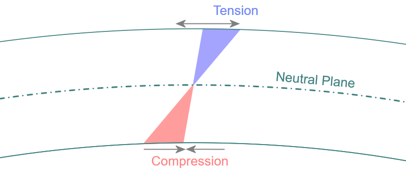
Additional folding accuracy is provided in the 3D Viewer environment
with the Neutral Bending Axis. This provides a bending ‘factor’ so
that the true length of the bent shape and tracks is calculated,
thus eliminating tension or compression.
Discover why thousands of companies around the world choose Pulsonix
"It is vitally important that we receive fast response and support from our software tools suppliers. We feel that WestDev are really interested in looking after their customers, and the support we get on Pulsonix is excellent."
Sascha Steiner - Tridonic Atco