
What's in Pulsonix 10.5
Constraint Area Definition in Schematic Editor
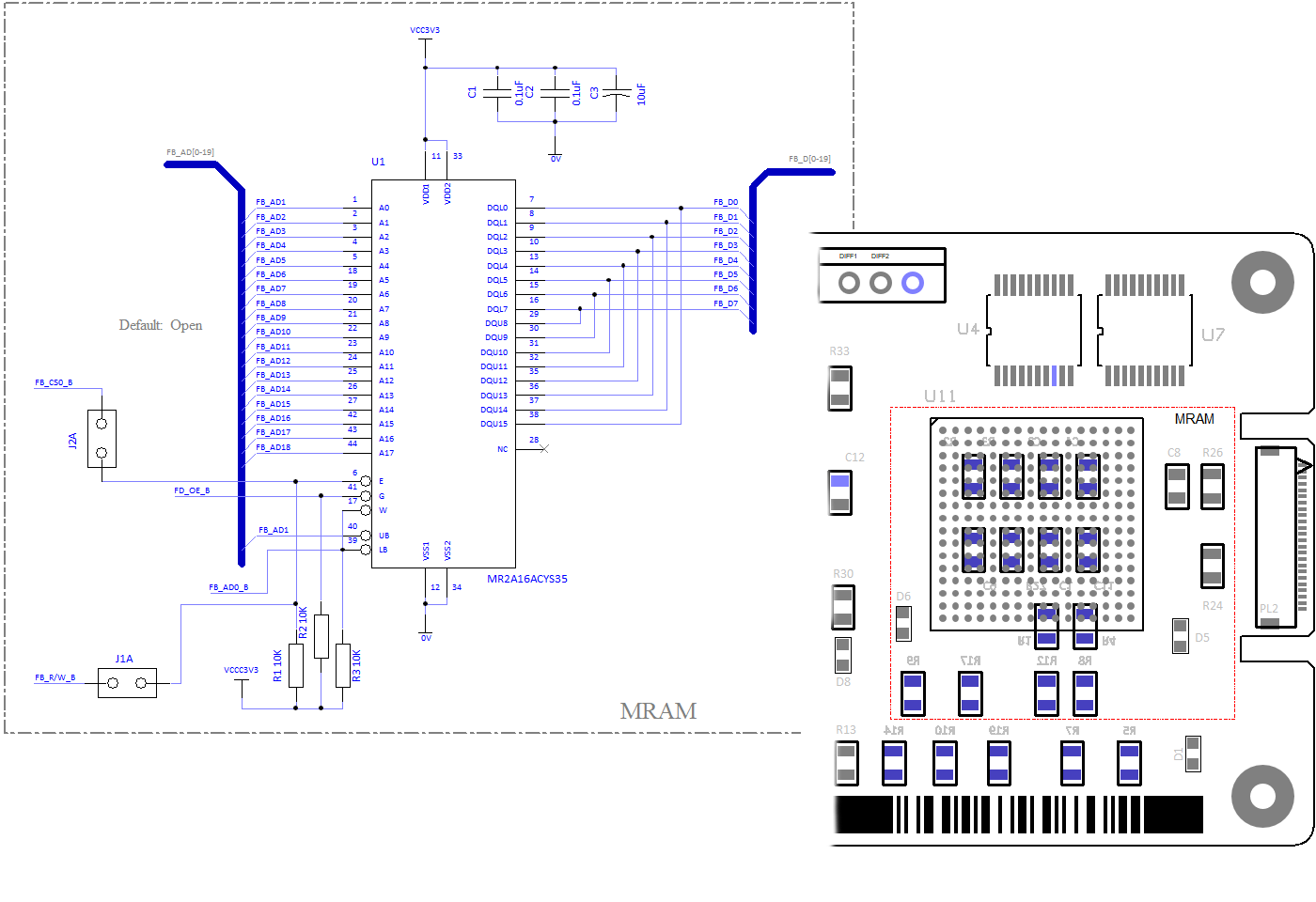
Add areas to your Schematic designs that behave as active regions used in the constraint manager to define rules without the need
to assign rules to individual items. Rules allocation is much faster and far more flexible. Rules can be Net or Component based and
subsequently passed through into the PCB design environment.
STEP 3D Preview - Exploded View and Clash Detection
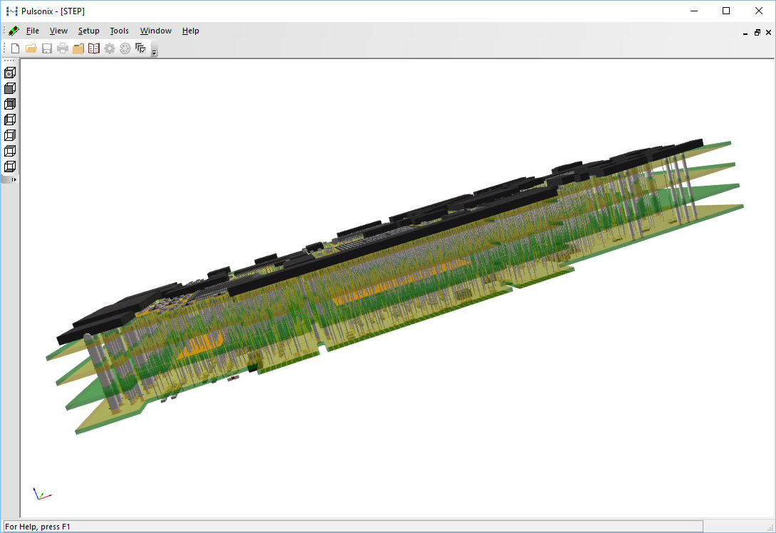
The 3D STEP Preview presents you with the ability to display an exploded view of your design so that internal layer structures can be inspected.
Clash markers show the precise location of rules violations and the rule in error. A measure tool enables distances between objects
in the 3D Preview to be viewed.
Component Place Rules
in PCB Editor
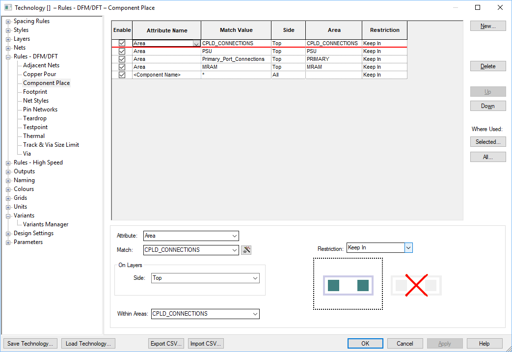
Component Placement rules can be defined using Areas or Attributes. With Areas defined in the Schematic design and Components then
assigned to them, the place rules can be used. Defining collections of critical Components means localised areas in PCB are utilised by the
Pulsonix placement tools and rules.
Multi Connect in Schematic Designs
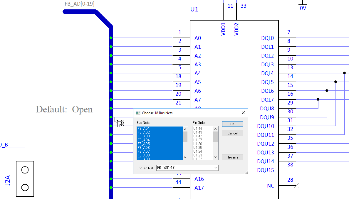
Following multi-selection of pins within the Schematic design, connections can then be drawn as a set of ‘bused’ nets. Drawing nets as a
collective save precious design time. These can be connected to another device and also to a bus item; weld markers indicate it can be connected
for abolute connectivity integrity.
Drill Drawing Layers
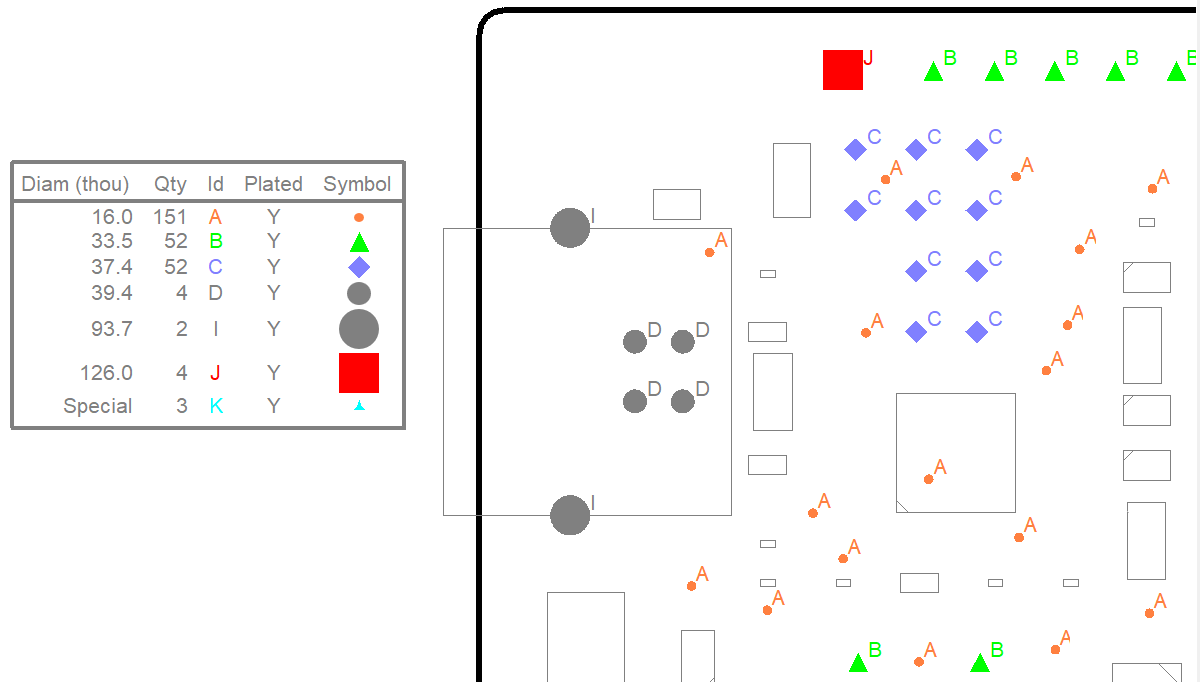
Drill drawing layers are available in the PCB along with drill idents, symbols and the drill table. This adds further documentation
detail to the design and complements the existing plotting mechanism for drill drawings. Coloured Drill Sizes can be used to define
drill idents by colour for further clarity and identification.
Dynamic Track Impedance Calculation
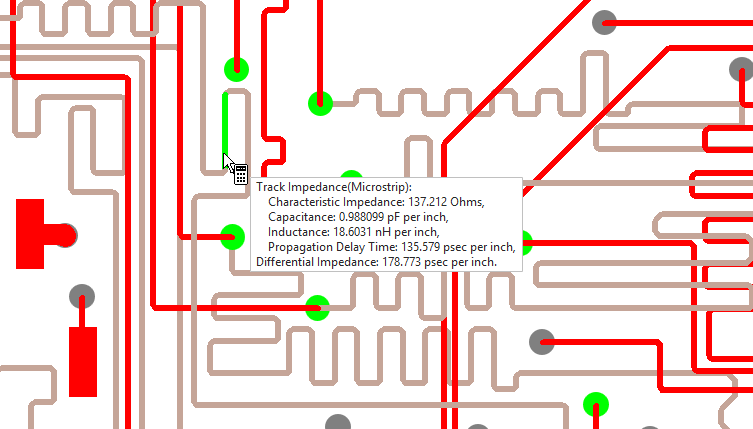
Track Impedance calculations can be displayed on-the-fly using the Design Calculator tool in ‘dynamic’ mode. All calculations are shown in
real time for a selected track with the impedance displayed in the headup display at the end of your cursor as a tooltip.
Data Migration
Pulsonix delivers the largest collection of free Import Filters available in the industry. Import Schematic and PCB Designs as well as the Libraries from your current system; retain your Intellectual Property with accuracy and precision.
And where an import filter for your product is not available, please contact us to discuss other options, such as rebuilding your designs from Gerber data and reverse engineering the PCB back into a working Schematic design to match!

Discover why thousands of companies around the world choose Pulsonix
"With an interface to our MCAD product - Solidworks, a 3D board can be forwarded to the mechanical department to generate an enclosure long before the first board is manufactured. This has helped a lot in shortening our development lead-times and is saving the company money."
Peter Goerlich - Durr Dental