

The Settings page defines model rendering options. You can define what parts of the board are rendered depending upon requirements.
Shortcuts
Default Keys: None
Default Menu: 3D Design
Command: 3D Settings
Locating this option
Available from: (PCB design) 3D Design menu > 3D Settings> Settings tab
Available from: (3D Viewer) 3D Design menu > 3D Settings> Settings tab
Using the dialog
On selection, any existing settings for the 3D view will be presented.
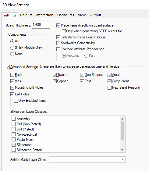
Board Thickness
Board Thickness: is the control used to define the thickness of the board in the output. If you have setup the thickness of each Layer in the PCB Technology then the value will be the sum of these. This can be overridden here if required but is not advisable.
Components
Using the Components selection, you can choose if All components are displayed in the 3D Viewer and exported to the output. You can also choose components that have (valid) STEP Models Only or None (no Components displayed or exported). Note, if STEP Models Only is selected, this also excludes 3D Packages or the creation of default package definitions.
Place items directly on board surface
Selecting the Place items directly on board surface will place components directly on to the board surface without leaving the usual tiny gap between the surface of the board and the component pads. This may be required for example if you need to make precise measurements of component coordinates in your 3D software.
With this switch enabled, you can further refine its use when Only when generating STEP output files. Checking this box means that the Preview will still include the tiny Z offset needed to ensure that there is no ‘dithering’ of the image as happens when two items try to occupy exactly the same Z coordinate, but the output file will omit this offset.
Only Items Inside Board Outline
When enabled, any items that are fully outside the extents of the board outline will not be included in the 3D Viewer or output to STEP. Any items inside the board outline, or overlapping the board outline will still be included as normal.
SolidWorks Compatibility
Select the SolidWorks Compatibility check box to refine the STEP file that is output so that it is suitable for import into the SolidWorks mechanical program.
With this check box selected, any flat shapes created are given a nominal height (thousandth of a millimetre) rather than leaving them as a flat face. Flat shapes are used for items like pads and copper. Previously, Solidworks has/had an issue with completely flat shapes. The only effect of this is that the STEP file output will increase in size.
With this button checked, the output of text will be suppressed and the Text box above in Advanced Settings will be greyed out as unavailable. This is the case for both the STEP output file and the Preview.
Override Attribute Precedence
Select the Override Attribute Precedence check box to globally override the attribute precedence option, defined in Design Settings - General.
If the Override Attribute Precedence check box is selected, then you can force which attribute the system always uses (Footprint or Part). Having this field set means that if the STEP Filename attribute has been assigned to both Footprint and Part, you can force which one is actually used.
Advanced Settings
If you want to include any specific design objects, check the Advanced Settings box to enable other settings. You should be aware that checking any of these will increase the generation time and the size of the resultant file and the generation time for the preview. The only special exceptions are for Text when using the SolidWorks Compatibility switch, Flexi Bend Regions, Areas and Comp (Component) Areas (see above).
Notes
Flexi Bend Regions, Areas and Comp Areas may increase generation time for preview, but will not impact the size of the resultant file as these items are not output.
If any of these settings are not enabled when generating the 3D Preview, then they won’t be available for display regardless of what the 3D Colours switches are set to.
A note about Text - The text check box is only available if the SolidWorks Compatibility check box is unchecked.
Pads indicates whether any type of pads are output to the STEP file.
Vias indicates whether vias are output to the STEP file.
Mounting Drill Holes indicates whether mounting drill holes are output to the STEP file. If checked, the mounting hole drills are created as cutouts in the board. By default only the board and the components will be output.
Drill holes indicates whether drill holes are output to the STEP file. If checked, drill holes are created as cutouts in the boards.
Only Enabled Items indicates that only drill holes for enabled items will be output to the STEP file. For example, if Pads are enabled and Vias are disabled, then drill holes for pads will be added to the board but will not for vias.
Tracks indicates whether tracks are output to the STEP file.
Copper indicates whether copper Shapes are output to the STEP file.
Doc Shapes indicates whether Doc Shapes are output to the STEP file.
Areas indicates whether general non-component areas and are not output to the STEP file.
Comp Areas indicates whether component areas and are not output to the STEP file.
Flexi Bend Regions can be displayed in the 3D Viewer and are not output to the STEP file.
Silkscreen Layer Class
You can choose the Layer Class to use for outputting the Silkscreen layer using the drop down list box displaying the Layer Class names in your Technology.
Solder Mask Layer Class
You can choose the Layer Class to use for outputting the Solder Mask layer using the drop down list box displaying the Layer Class names in your Technology.
Components in the Design and STEP Models
Manufacturers sometimes provide STEP models for their parts. These models can be downloaded, gathered into folders and associated with Pulsonix parts and footprints. The models can be viewed using the Library Manager STEP Models page.
Related Topics
3D Colours | 3D Interaction | 3D Enclosures | 3D View | 3D Output | 3D Layers | STEP Library