

The Pulsonix system can export design data in GenCAD 4.0 format. This format can used for exchanging data to test equipment or front end systems supporting test equipment. Please also check other newer formats supported by Pulsonix as an alternative.
Note: The GenCAD export is not on the standard license and should be requested from your local sales office.
Shortcuts
Default Keys: None
Default Menu: Output
Command: Output GenCAD
Locating this option
Available from: Output menu > GenCAD option
How To Use Output GenCAD
From the Output menu, select the GenCAD option, the dialog below is displayed:
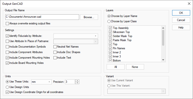
Output File Name
From this dialog, you can choose the name of the output file to be generated. The default for this name is the same as the name of your PCB design, with the file extension for GenCAD files as defined in the Options dialog.
Check the Always Overwrite check box if you want to suppress the “File Already Exists” prompt.
Settings
Identify Fiducials
Use this if you want to specify the Attribute name by which your Fiducial components are identified. Select the Attribute name from the drop down list.
Use Attribute In Place Of Partname
Check this if you need to use an attribute from the component other than its predefined Part Name to identify the type of component to the program that is reading the GenCAD file.
Include Documentation Symbols
Check this to include Doc Symbols in the output.
Include Component Attributes
Check this to include Component attributes as ‘property’ commands with each component. You may need to check whether your software can handle these properties when it reads GenCAD data.
Include Component Mounting Holes
Check this to include Mounting Holes that belong to Components (footprints).
Include Board Mounting Holes
Check this to include Mounting Holes that are part of the design (not belonging to Components).
Neutral Net Names
If this is checked then all user defined net names will output as numerical net names. This can be used to hide company specific net names.
Include Doc Shapes
If this is checked, all doc shapes in the design, in components and in doc symbols will be output.
Include Text
If this is checked, all text in the design, in components and in doc symbols will be output.
Units
The Units section provides controls that allow you to choose the units and precision for coordinates in the output file, and whether or not those coordinates are relative to the Design Coordinate Origin.
Use Design Coordinate Origin for all coordinates
If the Use Design Coordinate Origin for all coordinates switch is left unchecked then the coordinate origin (0,0) in the output file will align with the lower left position of the working area.
Layers and Layer Class
The Layers controls allow you to suppress layers from being output to the GenCAD file by unchecking them from the list. You can do this either by layer name, or by layer class. Note that the layer selection will only apply to shape-based items including component doc shapes, copper and tracks.
Variant
If your design has Variants, then the Variant controls allow you to choose which variant of your layout is to be output.