

Grids are used to define points or steps to which items can be “snapped” to when they are placed.
The Grids Setup dialog allows you to add or change the settings for any grids setup for the design.
All Grids are stored as a facet of your design and can also be saved as part of a Technology File.
Shortcuts
Default Keys: Alt+G
Default Menu: Setup
Command: Grids
Locating this option
Available from: Setup menu > Grids option, or Setup menu > Technology > Grids
Interactive Grids
Use the Interactive Grid tab to define which grid is used for which item type during interactive operations. The Tools Grid tab to define which grid is used for which item type during automatic operations. You may want to set all grids to be the same. Use the relative grid feature to ensure that grids are defined as multiples of a more basic grid. For example, the Component Grid could be a multiple of the Track Grid.
Tools Grids
Use the Tools Grid tab to define which grid will be used by automatic tools which require a grid of the given type - Component, Testpoint, Text, Track, Via and Panel PCB Item. These grids represent the default system grids.
Changing Grid Steps In Your Design
Grid steps can be changed at any time using different methods:
- Using Grid Steps by pressing the shortcut key defined <G>; at it’s simplest, it’s as easy as pressing the shortcut key for Grid Steps, typing the new grid value, and pressing Enter. You can also select a pre-defined named grid from this dialog, or
- Using Change Grid from the context menu and selecting a pre-defined grid by name.
Defining Grids Using The Grids Setup Dialog
Grids have more capabilities than a basic grid step, including definable origins, different X and Y steps, and scaling. These features are described below.
Grids are defined from within the Technology dialog and are presented as a list of grid names and values that can be named and edited.
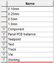
Name
Choose the grid you wish to examine or modify.
Pressing New, allows you to create a new Grid.
Pressing Delete, enables the currently selected Grid to be deleted. You can only delete a grid which is not Used, which means it is not currently defined as an Interactive or Tools Grid, or referenced as a relative grid. In the grid list above, the grid name is marked with a Y if it is used in the design.
Relative
Selecting a Relative grid allows you to define one grid to take its step value from another. For example, you might set the Via grid to be relative to the Track grid, with a Multiplier of 4. This would ensure that the Via grid is always four times the size of the Track grid even if you change the actual step value of the Track grid.
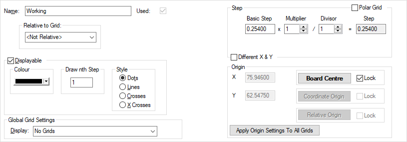
Step
This section of the dialog defines how the grid points are spaced across the design area. The simplest kind of grid has the same Basic Step between successive grid points, as shown in figure 1 below.
Sometimes it is useful to be able to make the grid steps smaller for a specific operation (perhaps to position several items close together) without losing the original basic step. Figure 2 below shows an example using a Divisor of 4, making each grid position just 0.25mm where the original Basic Step is 1.0mm.
Using a Divisor is a good way to produce a fractional grid, for example you may want to route two tracks through a 100 thou gap. You can achieve this by creating a grid with a basic step of 100 and a Divisor of 3. There is no accumulated rounding error using this method.
It is also possible to set up grids with different X and Y values, as shown in the picture above. Checking “Different X & Y” will display the additional controls needed to set up the Y grid values. These can be used to set the same grid combinations as for a normal “symmetrical” grid.
Figure 3 below shows a simple asymmetrical grid, with the Y grid step 50% larger than the X step. Figure 4 is more complex, with a sub-divided grid in X and a simple grid in Y.
Units
When using this dialog, the value typed for the Step will be the current Design Units. However, these can be changed to define the step in the units required, for example, design units in Imperial but you require units in Metric. You can either type the unit name after the value, so for example, 1.2mm, or 10thou, or you can select the units button at the base of this dialog which changes the units for you during your edit. Step values will always be converted and displayed as the design units defined regardless if what you type.
Origin
Settings in this section enable you to reference the grid origin.
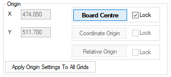
X, Y
The origin of any grid can be changed to a specific value or relative to another reference, such as the Board Centre or another system grid. The default origin is 0,0 (X,Y) which places the grid origin at the coordinate origin. Grid steps are measured from the grid origin, so for example, if the grid step is 5mm, and the grid origin is at 2mm, the first grid step after the origin is placed at 7mm.
Reference
If the grid is not defined relative to another grid, you can set the origin using the buttons to the right. These allow you to set the origin to specific points in the design, such as the centre of the board outline (Board Centre), the Coordinate System Origin, the Relative Origin or the Symbol Origin (when editing a symbol). A grid origin already set to one of these positions will be indicated by the appropriate button text being emphasised. Setting the grid origin is particularly important for Polar grids.
Lock
A grid origin may be ‘locked’ to a particular origin in the design by checking the Lock option next to the appropriate button. Once locked, the grid origin will automatically track any change in position of that type of origin in the design.
Apply Origin Settings To All Grids
If you are working with multiple grids that require the same origin settings, you can use the Apply Origin Settings To All Grids button. This allows the origin settings from the chosen grid to be applied across all other grids in a design when this button is selected.
The use of Apply Origin Settings To All Grids is also an effective way to reset all origins back to a desired grid default. For example, change one grid back to (0,0) and pressing Apply Origin Settings To All Grids resets all the grid origins.
If the grid is defined relative to another grid, some alternative options are available. Here we can see the origin coordinates of the grid which this grid is relative to. However, now they are greyed out to indicate that they cannot be altered in this context. The boxes to the right of these represent any offset we may wish to apply on top of the original, relative, origin. To the far right we can see the final sum of our original origin along with said offset, thereby representing the ultimate origin of the grid.
Polar
Polar grids are particularly useful for placing components on a circular board. Whilst moving a component on a polar grid, use the Auto Rotate command to rotate the component relative to its position on the grid. You can also use Construction Lines for this function as well.
To activate a polar grid, check the Polar Grid box. You should then define the number of radial steps. For example 8 radial steps would give one every 45 degrees, radiating from the origin. The concentric step is the gap between each concentric circle around the origin. The origin angle is the angle of the first radial, this effectively rotates the whole grid about the origin. For relative polar grids, only the grid origin position is relative.
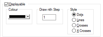
Displayable
Any grid in the design can be displayed on the screen, this also includes multiple grids at the same time. By checking the Displayable button, the chosen grid becomes capable of being displayed. Whether it is actually displayed is also dependent on whether grids are currently being displayed, using the Global Grid Settings described below.
There is an exception to this when the Display setting is set to Only Interactive Grids. See below under Global Grid Settings.
Colour
Once a grid is set as Displayable the Colour can be chosen.
Draw nth Grid
The display interval can also be set by changing the value from 1 in the Draw nth Step grid setting. You may wish to display perhaps only every 10th grid step to avoid cluttering the screen with too many grid points.
Style
The grid can also be displayed either as Dots, Lines, small horizontal Crosses or small diagonal X Crosses. The size of crosses are related to the size of the grid; the bigger the grid step, the larger the crosses will be.
Note for polar grids, the horizontal and diagonal crosses appear the same.
Global Grid Settings
As well as being able to set whether or not individual grids are displayable, by using the list labelled Display it is possible to select how grids are to be displayed generally. There are four possible options:
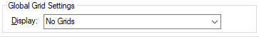
Display
- No Grids: means that no grids will be displayed.
- Grids: means that all grids that are set as Displayable will be displayed.
- Only Interactive Grids: means that any grid specified for an interactive operation will be displayed exclusively (even if the particular grid is not set as Displayable). When no interactive operation is being used the General Interactive Grid is displayed.
- Only Interactive Grids During Editing: with this mode selected, all grids that are set as Displayable are displayed until you use an interactive operation. Once an editing operation is used, the relevant Interactive Grid will used and be displayed.
Toggling Grids On and Off
you can toggle the display of grids to be on or off at any time whilst in the the design and outside this dialog. Use the shortcut key assigned to the “Display Grids (On/Off)” command, which by default is Ctrl+G.
Drawing Grids On Top or Under Design Items
There is a Design Option, Draw Grids Underneath Items which enables you to choose whether to draw the grids before or after the actual design items.
Technology File
The Technology File buttons allows you to Save and Load Technology Files. This means you could load a partial Technology and just load the Grids for example.
Units
The Units button allows you to locally switch between Metric and Imperial units whilst in this dialog. Once the dialog is closed, the units revert back to the original design units. If switching to different units to the design units, the value typed will be converted when you next enter this page.
Related Topics
Interactive Grid | Tools Grid | Grid Steps | Change Grid
Design Settings - Coordinate System | Technology Files | Technology | Units