

This page describes how to Differential Pair using the various modes and options.
Routing Differential Pairs
There two main routing modes that you would normally use for differential pair routing are Mirror Mode and Pairing Mode.
Each has it uses. Mirror mode is good to get started where both ends of the start point are aligned and the initial routing path would be uniformed. The Pairing mode is more useful where the starting points are not uniform and need to be routed ‘out’ to obtain an ‘exit’ first, then they can be routed as differential pairs.
If you wish to change the default pairing mode, select the Differential Pair Automatic Start Mode from the Options - Edit Track dialog.
Mirror Mode
-
Begin by routing a connection from one of the differential pair pins in the set. Move the mouse and add track segments until you reach the point where the pairing is to start.
Start Adding a Track
-
If the positions of the two start pads of the differential pair are suitable, you will be able to use Mirror Mode to automatically add the paired track at the same time.
After Start Mirroring Paired Track
-
The path will mirror the track you are adding about a centreline running between the pads. The two tracks will be kept apart using the Differential Pair Gap Rule if defined. If not, it will use the standard Track to Track Spacing Rule.
-
When using Mirror Mode, the initial segments and the mirror line will be perpendicular to the line through the start pads. This can be changed before you add the first corner by using the Rotate Mirror Angle, if available on the context menu, to rotate the mirror line by 45 or 90 degrees depending on the current segment mode.
-
Click the mouse when the tracks are the correct gap apart and in the position to start pairing. Note, if you want to add a corner when the tracks are the correct gap apart without entering pairing mode, press the shift key down whilst adding the corner.
-
You will find that you are now editing the centreline path between the paired tracks. The centreline of the gap between the tracks is used for editing and is placed on grid. The tracks are created either side at the required distance.
-
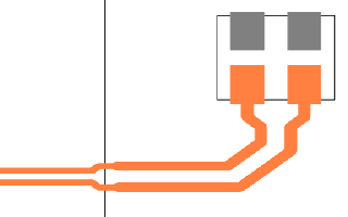
At any point you will also see Via position indicators (the larger circles) plus the smaller circles indicating where the tracks will be placed once a change layer has been performed.
During Routing, Via Positions Are Displayed
-
If you wish to view the centreline during routing, select the Show Centreline option from the Options - Interaction dialog.
The Centreline Is Displayed

-
If you have Show Legal Completion Path on in the Options - Edit Track dialog, you will see how the tracks will finish if you use Complete As Track or a double-click to finish.
The Finished Result Looks Like This
Changing Layers and Vias
-
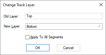
During routing, if you wish to swap the paired routing layer you can use Change Layer from the context menu.
If Online DRC is enabled and the vias would cause errors the pattern is not shown and the Change Layer option is not allowed at that point.
-
This will stop track pairing, add a via pair pattern to swap the tracks to the other layer, and then carry on pairing again.
-
The vias are added (optionally on the via grid) and the paired track is offset to ensure the gap centreline is in line with the point between the two vias. An appropriate track pattern is added between the vias and the paired tracks to fit in with the track and via spacings and current segment mode.
-
Moving the mouse as you move the cursor when adding paired tracks will optionally show you the actual via landing pattern along with the start positions of the next track pair if the layer would be changed.
-
The via pattern can be changed by right clicking the mouse and using the Via Pattern sub-menu on the shortcut menu. The following menu is displayed:
Use the top three commands to change the via positions.
Use Cross Over to make the tracks cross over each other within the pattern. Note an “X” is drawn in the via to indicate a cross over.
Use the next four commands to define a specific exit direction from the pattern.
The Auto Turn option can be used when changing layers to initially exit the vias straight, but as you move the cursor after vias are added, the pattern will change to exit left, right or backwards to best match the cursor position. Once you corner or backspace, the Auto Turn mode will be switched off.
If you do not need your vias to be placed on a via grid (for manufacturing purposes), check Allow Off-Grid Vias to let the vias be placed as close as possible with their mid point in line with the paired track centre line. This avoids the slight shift in the paired tracks to align them with the mid point between the gridded via positions.
Use Show Via Pattern to toggle the display of the pattern in the design.
You can place any on these options on a key, but there are two additional commands provided to help:
Using Differential Pair Via Pattern cycles between the three via patterns (if appropriate) and Differential Pair Via Exit Direction cycles between the four exit directions (again if appropriate).If you use the wrong pattern, or change layer in the wrong position, you can remove the layer change by using the backspace key.
Swapping Pairs
-
When using Pairing Mode, if the clone is on the wrong side of the path you can use the Swap Paired Tracks option to switch the paired tracks over.
Different Modes
-
If you did not use mirroring at the start, you can use the Complete Differential Pair Start option from the shortcut menu to route from the start pad of the second net to the paired tracks.
Use the Mirror Mode option to temporarily separate the tracks to go either side of an obstacle.
Whilst in mirror mode one of the tracks will be edited (shown selected) and the other will mirror its movement about a line between them. Movement of the tracks will automatically be restricted so that they do not become closer together than the differential pair gap.
Left click when they are close again to carry on pairing. You can undo this by using the backspace key.
After Start Mirroring Paired Track 
Move around obstacle and add corner to end mirroring 
Back in paired track mode 
Pairing Mode
- An alternative to Mirror Mode is to use Pairing Start Mode.
- This mode fundamentally the same as using the Insert Bus Route option in that it gathers the two tracks by single side routing to the two junctions representing the start of the paired section. Moving the cursor moves the junction pair to the required position, and left click starts the pairing. This mode is better than using mirror mode in that it can route around obstacles when gathering the tracks to the start of the paired section. The disadvantage with this is that one track may end up longer than the other which will need to be balanced later by lengthening the tracks on the other net.
- You can switch between the three modes using the context menu, which will also show which mode you are in. When you start routing one of the three modes will be used automatically for the differential pair. This is defined in the Add a Differential Track Using section of Options - Edit Track. Whilst editing, you can check what automatic start mode is currently set using the Editing Options sub-menu from the context menu. Use Next Diff Pair Start Mode to change the automatic start mode to use in the future The current start mode is shown in brackets.
Copy of an existing Differential Pair Via pattern
-
You can also choose to use a copy of an existing Differential Pair Via pattern when changing layer whilst adding paired tracks. You may have already created a pattern that you want to use, this can be copied and reused.
Before you start Differential Pair routing you have to choose the pattern to use. To do this first select all items in an existing pattern from the end of the paired tracks on one layer to the start of the paired tracks on the other layer. Using Frame Select with the Select If completely Framed option enabled will help ensure precise selection. Then, if needed, add any Ground vias that have been placed around the pattern (used for shielding) to this selection.
If the pattern is selected as required, you can then use Copy Diff completion Pair Pattern from the context menu to save it to a special location on the clipboard.
The pattern must contain Tracks and Vias on two nets, each net selection must contain a track that starts from a paired track on one layer, and then a continuous path from it to a track that ends on a paired track on another layer. This path can contain several micro-vias. The pattern can change direction and cross over. Then, when adding new paired tracks, you can now right click to use the Via Pattern sub-menu and choose Paste Diff Pair Via Pattern.
If the copied via pattern is suitable for this pair you will see all its vias as you move the paired tracks. Change layer and the copied via pattern will be inserted in order for you to change layer. If the pattern is not suitable (wrong gap between tracks, wrong layer, etc) then change layer will not be available until you switch the via pattern.
The via pattern option Paste Diff Pair Via Pattern will be remembered and will be used in future whilst the pattern is available on the clipboard. Changing layer back to the start layer will use the same pattern rotated about 180 degrees.
You cannot use Auto Turn or Drop Via with this feature. When you use change layer it is fixed to the layer that the chosen pattern ends on.
Drop A Via
-
An alternative to using Change Layer is to use Drop Via from the shortcut menu. This adds the two vias in the same way as described above, but does not change layer. The tracks are continued on the same layer as they were on. This is useful when adding a differential pair branch, for example when using DDR2 or DDR3 flyby routing, to drop a via pair near to each of the other branch target pads, ready to be routed when completing the other branches. Prior to dropping the vias, you may need to use the Swap Vias option from the Via Pattern shortcut menu if available. If used this will swap the positions of the two vias which may end up better suited for routing to the target pads at the end of their branch. The dynamic via position that will be on the net of the track you selected to edit (shown on the status bar) is drawn in the select colour, and the other via position is indicated using the highlight colour.
Another way to insert differential pair vias is to use the Finish On Via option from the shortcut menu. The differential paired tracks can be continued from the vias at a later stage. This option is also useful if the differential pair ends on two branch points. When the vias are inserted you will be asked if you want to change them to branch point vias, replacing the documentation symbol branch points.
Finishing Paired Tracks
There are several alternative methods of finishing the paired tracks you have just added as follows:
-
Use the Finish Here option on the shortcut menu to leave the track pair where they are and exit Add Track with dangling connections to the end pads.
-
Use the Differential Pairing command (shown as Pairing Mode on the shortcut menu) to stop the pairing at that point and carry on editing one of the tracks.
-
Use the Complete As Track command to route the two dangling connections to the destination pads.
Before Complete As Track After Complete As Track 
-
If the destination pads are in suitable positions, use the Mirror Mode option to separate the tracks and finish by clicking on one of the pads. This will also finish the mirrored track if it is over the other differential pair end pad. Before mirroring, move the end of the centreline you are adding onto a line bisecting the target pads to ensure the mirrored sections of track can both end on the pads. The centreline being added is gridded, but should also snap onto the bisecting line even if it is not on the grid.
Before Start Mirroring Paired Track 
After Start Mirroring Paired Track 
Move over pad and click to finish 
-
When adding a track pair with dangling unrouted connections going to the start of another track pair, adding a corner when the paired track ends are directly over the static paired track starts will finish the current track pair and join it to the static track pair.
Adding track pair 
Move cursor over start of other track pair 
Click to finish, pairs will be merged 
If the paired tracks were not completed, continue adding track segments on the original net until you reach the destination pad. Then route the second dangling track separately.
With both methods you can create any number of paired sections of track along the path. You must complete the gaps in the “clone” track manually.
Adding Odd Angled Differential Paired Tracks
There is a technique for routing differential pairs out of pads at odd angles.
Do this by start mirroring a Differential Pair track from two pads that are at an odd angle (not a multiple of 45 or 90 degrees depending on the current segment mode), you will be presented with a warning dialog asking if you want to enter Restrictive Movement mode to add segments that are perpendicular to the line through the start pads.
Choose Yes to do this. The restrictive movement angle will be automatically set and the track segments will be at the correct angle. If this is an operation you do often on odd angled components, then you can switch this warning message off using the check box on the dialog.
When adding corners the restrictive mode stays and you can turn in 45 degree steps relative to the start angle. When the two tracks are close together and you click, it will enter adding paired tracks still in the restrictive mode. Add a segment or two and then use the context menu to switch Restrictive Movement off and now you can add the segments in your normal segment mode.
If you chose No to the warning message, the mirrored segments will be added from the pads in a direction that is a multiple of 45 or 90 degrees closest to where you clicked to start mirroring.
Adding Spurs in Paired Tracks
You can finish a single track on a Differential Paired track segment provided the segment is not an arc and is on the same net. To allow this happen, in the Technology - Differential Pair dialog the pair must have the Allow Spurs rule enabled. With the single track end over the Differential Paired track to connect to, on drop, it will unpair a small section of the segment and join the track to it.
Adding Broadside Paired Tracks
Broadside paired tracks follow exactly the same path, but are on different layers. To add broadside pairing, you need to change the layer of both or one of the tracks before you can add the paired segments.
When adding a broadside differential pair track, using Start Differential Pairing will prompt for the Broadside Clone Layer. This is the layer that the copy of the track being added will go on. You will not be able to see the broadside clone as it is added underneath the track being added.
When using Mirror Mode from two surface mount start pads, mirrored tracks will be added but you will not be able to start pairing yet and the defined gap will be maintained. Whilst mirroring you can change layer to set the track being edited to a different layer to the broadside clone, and then the tracks can be brought together and pairing can start.
If you start mirroring from through hole pads or vias, you will be asked for the layer for the broadside clone and the mirrored track will change to that layer. Now the mirrored tracks will be allowed to come together and when this happens a click will start broadside pairing, one track on top of the other.
When adding differential pair tracks that allow both coupling types you can switch between them using Switch To Broadside Coupling or Switch to Edge Coupling from the shortcut menu. This can only be done when not actually adding paired tracks, so you have to stop pairing, change coupling type and start pairing again. When switching to broadside coupling you will again be asked for the layer for the broadside clone track.
For broadside coupling the paired length will be calculated only where one track is completely over the other, but if both edge and broadside coupling is allowed, both types of paired sections will be added together to give the total figure.
Editing Options for Paired Tracks
When editing or moving existing sections of paired tracks you will actually be editing the centreline path between the tracks. The tracks themselves are updated automatically to follow your edited path. The centreline can be toggled on and off in the Interaction Options dialog. This is the line that you are actually editing on the current grid. This helps with seeing that it is on grid and shows the selected dynamic segments. The line is removed as soon as the edit, move or move corner is complete.
Another option, Keep Correctly Paired can be used to stop doubling back and acute corners when adding or editing paired tracks and bus routes, where the tracks end up curved or further apart than the required gap. This mode can be a bit restrictive as it only allows valid track segments.
Editing Paired Tracks
Using double click on the junction at the end of a paired section, or selecting the junction whilst in Add Track mode will allow you to add additional paired track segments at the end of the existing track pair. If you want to add a single track an the end of one of the paired tracks, enter Add Track and click on the connection attached to it. If there is no connection attached use Optimise Nets to re-create the connections on the net. If there is still no connection attached, in Add Track press the Ctrl key down whilst clicking on the end of paired track.
Removing Differential Pairs
A paired section of track (or a selected part of it) can be unpaired using the command Differential Pairing whilst in select mode. This is shown as Remove Differential Pairing on the shortcut menu. The tracks can then be edited separately. Alternatively you can use the Unroute Track Segments option to convert the selected section of paired track back to connections.
In Select Mode you can use Add Differential Pairing on a selected unrouted connection between two sections of paired tracks to automatically complete the pairing between the sections.
Whilst editing tracks in a differential pair you can display the length difference between the two halves to the pair along with any maximum value you have defined on the pair. See Show Track Length Limits for more details.
Editing Differential Pairs into Areas
When adding differential paired track segments and you cross an Area boundary that has different track styles in Net Styles, or different differential pair gaps defined, the pairing is automatically stopped on the near side of the area border and started again on the far side with two transition tracks added over the border joining the ends of the paired sections together. If it was a mistake entering the area, use the Backspace key to remove the area transition Tracks and revert to editing the original paired tracks.
Related Topics
Differential Pair Nets Rules | Differential Pairs | Differential Pair Gap Rules | Spacing Rules | Set Default Pairing | Show Length Difference | Differential Pairs Spreadsheet | Serpentine | Colours - Highlights | Design Rule Checking