

This page can be found on the Simulation Parameters dialog. Use it to set up a number of commonly used simulation options.
The simulator features a large number of option settings although the vast majority can be left at their default values for nearly all applications. A few option settings can be set via the Simulation Parameters dialog box and these are described in the following sections. The remainder can be controlled using the simulator’s .OPTIONS control.
See section on Convergence in the Pulsonix-Spice Users Guide for a discussion of the tolerance options.
Shortcuts
Default Keys: None
Default Menu: Simulation
Command: Simulation Parameters
How To Change Simulation Options
Select the Simulation Parameters option from the Simulation menu and pick the Options tab.
The following page will be displayed:
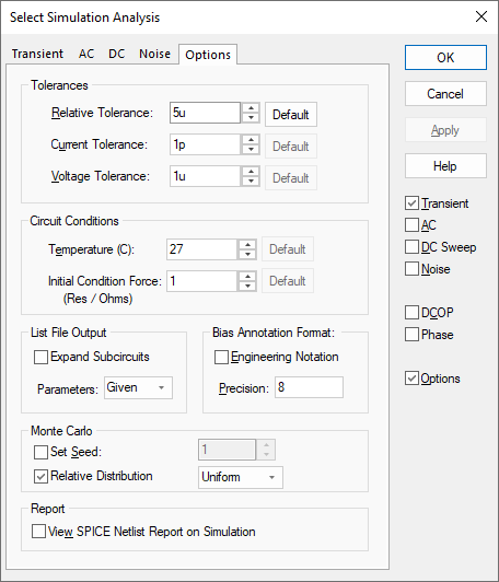
Tolerances
Relative Tolerance
This is the relative tolerance that must be met for each analysis point. Reducing this number will improve accuracy at the expense of simulation time or/and convergence reliability.
For example, if set to 0.001 (the default value) and the value of a voltage is 3.2V, the accuracy will be 0.001 x 3.2 = 0.0032V.
If you are simulating oscillator circuits it is recommended to reduce this to 0.0001 or lower.
Current Tolerance
This is the absolute tolerance for currents and therefore has units of Amps. The default value is 1pA. This basically affects the tolerance for very low values of current.
It is sometimes desirable to increase this for circuits that carry large currents(>1A) to speed the solution and aid convergence.
Voltage Tolerance
The absolute voltage error tolerance, default value is 1µV.
Circuits with large voltages present (>100) may benefit from an increase in this value.
Circuit Conditions
Temperature - Circuit temperature in °C. Some devices can override this on a per instance basis.
Initial Condition Force Resistance - Initial conditions apply a voltage to a selected node with a force resistance that defaults to 1W. This option allows that force resistance to be changed.
List File Output
Expand Subcircuits - If checked, the listing of expanded subcircuits will be output to the list file. This is sometimes useful for diagnosing problems.
Parameters - Controls the level of model and device parameter output to the list file. Options are:
| None | No output. |
| Brief | Only values defined by an expression are output. |
| Given | The default. Values that are explicitly defined are output. |
| Full | All parameter values are output including defaults. |
Bias Annotation Format
Use these controls to alter the format that will be used for the DC Operating point values displayed on Bias Voltage Markers in the design.
Enabling the Engineering Notation checkbox sets the format to use the standard multiplier suffixes (e.g. m=1e-3 u=1e-6 etc).
Simulation will need to be run again to change the values shown in the design.
Monte Carlo
Set Seed
Set Seed - Seed for pseudo random number generator used to generate random numbers for tolerances. The random variations are created using a “pseudo random number sequence”. The sequence can be “seeded” such that it always produces the same sequence of numbers for a given seed. In Monte Carlo analysis, the random number generator is seeded with a new value at the start of each run and this seed value is displayed in the log file.
Using the Set Seed option it is also possible to fix the first seed that is used. This makes it possible to repeat a run. To do this, note the seed value of the run of interest from the log file then enter the seed value in the Monte Carlo section of the dialog.
The first run of each Monte Carlo analysis will use the same random values as the run from which you obtained the seed value in the log file. Note this assumes that only changes in values are made to the circuit. Any topology change will upset the sequence.
This technique is a convenient way of investigating a particular run that perhaps produced unexpected results. Obtain the seed used for that run, then repeat with the seed value but doing just a single run. You will then be able to probe around the circuit and plot the results for just that run.
Relative Distribution
Relative Distribution is a statistical setting. On selection, choose between Uniform and Gaussian to define how do you want the parameter selection for the Monte Carlo analysis to be set. The presents the possibilities of uniform distribution (with a higher chance of seeing extreme conditions) or Gaussian, which would more closely resemble the spread of characteristics found in real life.
The Monte Carlo setup allows the desired tolerance spread to be specified. If the Uniform option is chosen, the random allocation of values between the allowed extremes will be uniform, so there’s an equal chance of a value being at either limit as there is of it being at its nominal value. This is good if you want to get an idea of how the circuit is likely to perform in a worst case scenario, as the values are more likely to be off kilter than would be normal in the real world.
The Gaussian distribution is a more realistic simulation. Based on statistical deviation, there’s a characteristic hump, almost sinusoidal, that defines the spread of values from the centre. It’s more realistic because manufacturer’s tolerances have to be based on the worst case production scenarios, whereas in fact the values will typically be much closer to their nominal value than that, so the actual deviation from the design parameters will be less. This is useful if you want to get an idea of how a design will work in practice rather than trying to find out how it could go badly wrong.
Report
View Spice Netlist Report On Simulation - Every time a simulation is performed, a Spice netlist is written from the design for the Simulator to pick up. A report is generated containing the simulation parameters and listing any errors or warnings found whilst creating the Spice netlist. These tend to be comments about missing or incorrect component Spice values. Errors and warnings about suitability for simulation are given in the Simulator’s Command Shell window.
Select this check box to view the report when a simulation is run.
Other Simulator Options
The Simulator has a number of other simulation options. To use these, look up the correct command in the Simulator Help, and enter them using the Extra Simulation Data dialog.
Related Topics
Bias Voltage Marker | Extra Simulation Data | AC Sweep Analysis | DC Sweep Analysis | Multi-Step Analyses | Transient Analysis | Phase | Simulation Parameters | Sweep Modes