

Once in the 3D Viewer, multiple boards can be repositioned using the Fold Board command. These are non-flexi boards. If using flexi boards, use the Fold flexi Boards command.
The ability to fold boards is enabled when a pair of Board Origins are inserted into the PCB design and the Board 3D Origin set with folding parameters.
Shortcuts
Default Keys: None
Default Menu: 3D Design
Command: Fold Board
Locating this option
Within the 3D Preview window, it is available from: 3D Design menu > Fold Board option
Using the Fold Board option
You must run the 3D Viewer option from the 3D Design menu from within the PCB design editor first, this will create you a 3D Preview.
Now you will have two or more, multiple boards displayed. If you only have one board, this option will not be available.
You can run the Fold Board option from the 3D Design menu. This option will toggle between the folded status and not folded status. Once folded, you are able to move components on the folded board, and can also move the folded board itself. Moving the folded board will result in the offset values defined in Board 3D Origin Properties (for the corresponding board origin) being altered to match the fold transform that will be required. 3D view will regenerate to update the positions of all the items on the folded board.
With multiple boards displayed, you can now rotate the designs in the viewer and also run Clash Detection on them.
Setting up the boards to use the Fold Board option
Using a two board example where one will be folded on top of the other so that a fit and clashes can be detected. Below is the process used for this example:
-
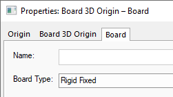
Select Board One, this will be defined as Rigid Fixed in Board Properties.
-
Select Board One and from the context menu, select Insert Board 3D Origin. Place the origin where you want the movement to be taken from. This is your reference point.
-
The Board Origin Properties dialog will now be displayed from where you can set the additional information for naming and positioning your board relative to the location when the pair of origins are aligned.
-
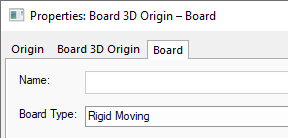
Board Two will be defined as Rigid Moving in Board Properties. This indicates it is the ‘moving’ board.
-
Select Board Two and from the context menu, select Insert Board 3D Origin. Place the origin where you want the movement to be taken from. This is your second reference point.
-
If you have more boards that you wish to move, add more pairs of Board 3D Origins.
-
Now that you have two (or more) Board 3D Origins, change the Properties of the second moving origin so that it can be moved.
-
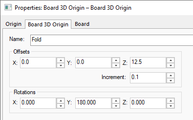
When the board is moved in the 3D Viewer, the Offsets will position the board relative to the other one. The Rotations will inform the moving board how much to ‘flip’ and in which direction.
-
For our example where the position of the Board Two is required on top and facing Board One, the Z offset positions it 12.5mm
Related Topics
3D Viewer | Insert Board 3D Origins | Properties - Board 3D Origin | Clash Detection