

A Differential Pair consists of two pairs of pins on two different nets which would be routed along side each other (Edge Coupled) maintaining a constant gap as much as possible.
Differential Pairs can be created in the PCB design, or defined up front in the Schematic design during the design phase. If defined in the Schematic design they will be automatically transferred to the PCB during Translate To PCB or when the designs are synchronised.
Paired tracks are locked together and separated using the Track to Track spacing gap or using a defined differential pair gap. You do not have to Pair the tracks when routing, but defining them as differential pairs does offer advantages:
- Adding paired tracks guarantees them to be the correct distance apart, or in the broadside case, directly on top of each other.
- Paired tracks are gridded along the centreline of their gap, making it easier to route from the ends of paired sections to the differential pair pads with the same track length.
- Subsequent editing of paired tracks treats them as ‘one’ entity and keep them locked together at the correct gap.
- You can highlight the paired sections, making it easier to view. The paired sections will follow
- You can Serpentine the paired segments, either both sides together to lengthen both tracks, or one side only to correct skew length differences.
Differential Pairs can also be chained together, using terminating components. Linking differential pairs into chains allows length rules to easily be applied to the whole chain.
Facets of a Differential Pair before you start
Many facets of a differential pair can be defined. As a minimum for the pair of nets to behave as a differential pair, it must be defined in Differential Pairs dialog and must have a differential pair Name. all other facets are optional but add value to the pair and provide you with additional rules and control.
Differential Pair Names
Each Differential Pair (Diff Pair) can be named to uniquely identify them and to describe their purpose within the design. Alternatively, their names can be auto generated using the names of their four pads by the application.
Defining Differential Pairs
There are two methods for defining Differential Pairs:
Using the Differential Pairs dialog you can ‘manually’ create the pairs by selecting pairs of pins, or you can pre-select the pair of nets in the design. If you pre-select nets in the design, these will be added when you press the New button on the dialog.
You can define Differential Pair Nets Rules that can then be used in the Differential Pairs dialog to automatically create and name your differential pairs in a Schematic or PCB design. If you have many multiple differential pairs to define, then this is the easiest and least error prone mechanism to create them.
Track Widths Used for Differential Pairs
The default track widths and via styles to be used for differential pairs can be defined using the Net Styles dialog.
Spacing and Gap Rules Used
The Track to Track Spacing Rule can be used for differential pairs, but there is also a specific differential pair gap rule that defines the spacing between the paired tracks. If both rules are defined, the differential pair gap rule is used.
Skew Rules
The maximum allowed difference in length of each ‘side’ of a differential pair can be defined by a skew rule.
Track Length Rules
Differential pairs can be assigned a Track Length Rule, and can be included in a Track Length Match Rule to match the lengths of a set of differential pairs.
Track Length Match Rules
You can define the Track Length Match Rule so that sets of differential pairs can be matched against each other.
Track Length Indicators
Adherence to defined rules can be displayed whilst editing the Differential Paired tracks using the dynamic length limit indicator and head-up display.
Design Rules Checking Differential Pairs
At any point during design, if any rules are defined for differential Pairs, they can be checked as part of the design rule checking tool.
Differential Pair Colours
You can highlight nets that are defined as Differential Pairs but unrouted, and ones that are routed as Paired tracks using a colour defined the Colour Highlights dialog.
Setting up for Track Pairing
There are a number of ways of producing the paired tracks for a differential pair.
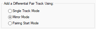
- Single Track Mode - Adds the single track you are editing and does not route the track on the ‘other’ net.
- Mirror Mode - Adds a mirrored copy of the track you are editing to the other net of the pair. Movement of the tracks will automatically be restricted so that they use the differential pair gap if defined. Once close, left click the mouse to start pairing.
- Pairing Start Mode - If you have routed ‘out’ of an area, this mode gathers the two tracks by routing to two junctions representing the start of the paired section. Moving the cursor moves the junction pair to the required position, and left click starts the pairing.
The starting mode for pairing can be defined using the Differential Pair Track mode in the Edit Track Options dialog. Mirror Mode is the default set when the application is first installed but you can change it using in Options or from the context menu when you select a differential pairs net or track to route.
Creating Differential Pairs
Differential pairs are created using the Differential Pairs dialog in Technology. From here, you can name them and define which pads or branch points they Start and End on. You can also provide the differential pair Name that identifies the pair. This is the process of defining the ‘pairs’. Routing them is described further down.
Manually Creating Differential Pairs
- Using the Differential Pairs dialog you can ‘manually’ create the pairs by using the New button.
- You must then select the First Pin Pair: net name from the list, then choose the Pin: for each ‘end’ of the net
- Next, select the Second Pin Pair: net name followed by the two sets of Pins:.
- Name the Diff Pair Name: to complete the pair.
- You can add extra information to the pair by choosing additional options from the dialog.
Alternatively (as an easier method):
- You can pre-select the pair of nets in the design that will make up the differential pair.
- For pre-select nets, when you press the New button on the Differential Pairs dialog, these will be added as the First and Second net name along with their Pin start and ends.
- The Diff Pair Name: will be automatically created matching the pin pairs. You can rename this to a name that is more reflective of the differential pair or its function.
Creating Differential Pairs using Rules
You can define Differential Pair Net Naming Rules that can then be used in the Differential Pairs dialog to automatically create and name your differential pairs in a Schematic or PCB design. If you have many multiple differential pairs to define, then this is the easiest and least error prone mechanism to create them.
Once the rules have been defined, use the Create Pairs From Rules button on the Differential Pairs dialog to apply the rules to create new differential pairs. You can also use these rules to apply new names to existing differential pairs defined.
Routing Differential Pairs
The two routing modes that you would normally use for differential pair routing are Mirror Mode and Pairing Mode.
Routing differential pairs is described here.
Finding Differential Pairs
Differential pairs can be found in a design using the Rules Spreadsheet (see next section) or by using the Find Bar. All pads, branch points, tracks and unrouted connections in the differential pair will be selected or highlighted.
Differential Pair Spreadsheet
The Rules Spreadsheet bar provides a method for viewing information about all differential pairs in a dockable modeless bar.
The spreadsheet is kept up-to-date whilst you edit the design allowing you to instantly review information on multiple pairs in order to help make the correct design editing decision. The main use of the bar is to indicate differential pair rule failures as they happen, so they may be quickly corrected or avoided.
Other uses for the spreadsheet is to provide an alternative method for finding and selecting particular parts of differential pairs in the design, and to directly edit some rules on a selected pair without having to first find it the technology dialogs.
Differential Pair Report
You can use the Reports mechanism to generate a report of all the differential pairs in the design, showing the rules defined for each pair.
In a PCB design this report shows the total track lengths and paired track lengths for each completed pin pair. The actual value is shown alongside the required value for each of the rules, indicating where there is an error.
Alternatively you can use the Report Maker to format your own differential pairs report.
Related Topics
Colours - Highlights | Design Rule Checking | Differential Pairs Spreadsheet | Editing Tracks | Set Default Pairing | Show Length Difference | Serpentine | Technology - Differential Pairs | Technology - Differential Pair Gap Rules | Technology - Differential Pair Nets Rules | Technology - Spacing Rules