

A Layer Change Length is an additional length provided to a signal when passing through a via or pad. By default, track lengths are calculated without taking any account any additional layer change lengths. Where track lengths are critical, the rules on this dialog enable you to specify additional lengths for vias and pads.
The rules on this dialog are used in conjunction with the Track Length Rules or Track Length Match Rules.
Shortcuts
Menu: Setup
Default Keys: T
Command: Technology
Locating this option
Available from: Setup menu > Technology option > Rules - High Speed > Layer Change Length page
Using the Layer Change Length page
The general rule matching mechanism used on this dialog is described here.
Navigation
The buttons to the right side of the dialog are used to navigate the grid, the general common buttons are detailed on the Technology Navigation page.
Using the editing pane
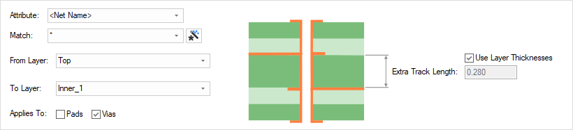
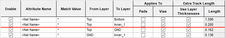
Attribute Name & Match Value
Define the Attribute Name and Match Value match attributes of a net. You can match the inbuilt attributes <Net Name> or <Net Class Name> to create net specific rules.
From/To Layers
From and To Layers are for the entry and exit layers of the track (which could be less than the span of the pad or via).
Applies To
The rule can apply to just Pads, just Vias or both.
Extra Track Length
The Extra Track Length is either calculated from the layer thicknesses, or can be specified as an explicit value by unchecking this option and typing the value required. If you have accurate layer thicknesses defined, you would use these.
Rule Usage Precedence
The appropriate layer change rule is found for each net by working down the list of rules until the first match is found. Hence, the order of the rules is important. A match is when the specified Attribute Name and Match Value match an attribute of a net. The net must have the given attribute, and it’s value must wildcard match the value. In particular, you can match the inbuilt attribute <Net Name> and <Net Class Name>. When a net is matched, the rule applies to all the pads, vias, etc on that net. The layer range in the rule is also matched to the entry and exit layers of the track (which could be less than the span of the pad or via). The rule with an exact layer range match will be used as preference.
For a terminating pad, the length specified by this rule is the additional length to get the signal to the surface, so the From layer is the electrical layer on the side of the component (i.e. top or bottom electrical layer).
Composite Via Spans
A special note should be made if you are using composite micro-vias; A good practice is to define a Layer Change Length rule for each via layer span within the composite micro-via span.
Pin Package Length Attribute
Using the in-built <Pin Package Length> attribute, you can define an internal length for the device. This attribute is added to one pin on a component with the value representing the internal connectivity length from the board surface through the package, for example 2.5mm. This will be in addition to any layer change value.
Export and Import CSV
Use the Export CSV button to export the data in your PCB design into a CSV format file. Using the Export CSV option will provide you with a formatted template ready for you to edit in your own data.
Use the Import CSV button to import data back into the PCB design using a CSV format file.
The data in the file represents a spreadsheet of dialog contents with the data headings along the top row.
Units
The Units button allows you to locally switch between Metric and Imperial units whilst in this dialog. Once the dialog is closed, the units revert back to the original design units. If switching to different units to the design units, the value typed will be converted when you next enter this page.
Related Topics
Technology Overview | Using Dialog Grids | Track Length Rules | Track Length Match Rules | Technology - Layers | Technology - Layer Spans | Design Rule Check | Export CSV | Import CSV