

The Phase option can be found on the Simulation Parameters dialog when running AC Sweep analysis.
Selecting the phase check box on the AC Simulation Parameters dialog means that the phase will be plotted on the same graph as the voltage on the same x-axis (with a different y-axis), so the graph has 2 y-axis. If only a phase plot is required, after simulation (from the Simulation menu), select the Random Probe then Probe Voltage Phase from the context menu.
Shortcuts
Default Keys: None
Default Menu: Simulation
Command: Simulation Parameters
How To Setup AC Sweep Analysis Parameters
Select the Simulation Parameters option from the Simulation menu and pick the AC tab.
The following page will be displayed:
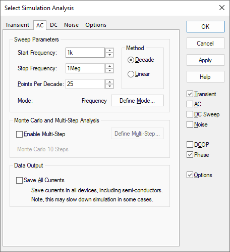
Sweep Parameters
Start and Stop Frequency - Defines sweep range stop and start values
Method - Determines how the frequencies within the sweep range are spaced. As x axis will be logarithmic Decade is most common here
Points per decade, Number of points - Defines sweep range. The number of points of the sweep is defined per decade for a decade sweep. For a linear sweep you must enter the total number of points.
Define Mode - Sets up desired sweep mode. AC analyses repeats a single analysis point while varying some circuit parameter. See Sweep Modes for details.
Monte Carlo and Multi-step Analysis
AC analysis can be setup to automatically repeat while varying some circuit parameter. See Multi-Step Analyses for details.
Data Output
Check the Save All Currents box to enable the output of all current data including semiconductor devices. If this box is not checked the current into devices such as transistors and diodes will not be saved. In AC analysis the CPU time required to output data can be very significant relative to the solution time, so you should be aware that checking this box may slow down the simulation significantly.
Note that this check box only affects AC analyses.
Note:
It is important to note that only small-signal frequency effects are calculated. Although the non-linear characteristics of the circuit are used to calculate the bias point and also the various gains and impedances at that bias point, these non-linear effects are not considered when subsequently calculating the frequency response. So apart from scaling, it makes no difference to the result what amplitude a single AC source has.
Related Topics
DC Sweep Analysis | Multi-Step Analyses | Noise Analysis | Transient Analysis | Simulation Parameters | Sweep Modes