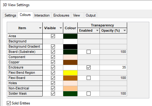
The Colours dialog defines all colours used within the 3D View so you can define and customise your own colours for the 3D Viewer.
Shortcuts
Default Keys: None
Default Menu: 3D Design
Command: 3D Settings Colours
Locating this option
Available from: (design) 3D Design menu > 3D Settings> Colours tab
Available from: (3D Viewer) 3D Design menu > 3D Settings> Colours tab
Using the dialog
On selection, any existing settings for the 3D view colours will be presented.
The colours used in the 3D View can be changed to suit your own requirements. Using this dialog you are able to define colours for categorised models, enclosures and the background.

Visible
A Visible column is available to show or hide all items of that type in the 3D Viewer, for example, disabling Non-Electrical visibility will hide all non-electrical items), without the need to regenerate the entire view. This does not affect which items are output when using the Output STEP or Output STL options; it only affects which items are currently shown in the viewer.
Transparency
The Transparency of certain items can be Enabled, and will need an Opacity % value in the range from 0 to 100% (0 being fully transparent and 100% being opaque).
Colours
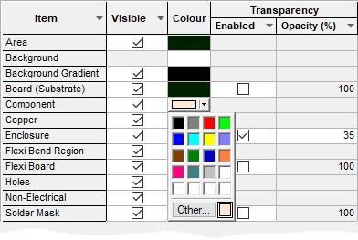
To change colours for any of the categories shown on the dialog, simply click on the drop-down list alongside the category name, and choose the colour you wish to use.

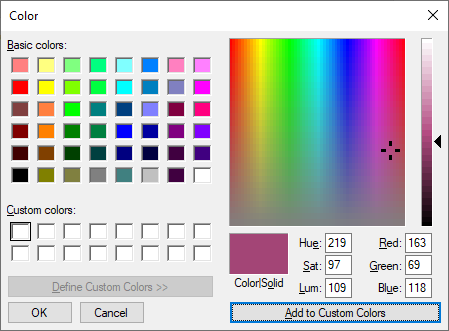
If you want to use a colour that is not shown on the list, choose the ‘Other..’ entry at the foot of the list, to access the standard Windows colour picker dialog.

What these Colours Are Used For
- Areas: height check areas use this colour, and are drawn as wire frame shapes at the correct height above or below the board surface.
- Background: this is the background colour of the 3D view window.
- Background Gradient: this is the background colour when Background Gradient: is enabled.
- Board (Substrate): used to draw and fill the board outline. Boards in 3D view are drawn filled, to give a more realistic representation of the actual circuit board.
- Components: this is the colour used to draw the default component body for those components which do not match up with a 3D Package library definition or a STEP model that contains a colour (not all do). It first checks for a STEP model linked to the component, if this does not have a colour then this colour will be used. If a STEP model is not linked to the component it will try to find a matching 3D package definition, and if one does not exist it will create a default one which will use this colour.
- Copper: pads, tracks and other items on electrical layers are drawn in this colour.
- Enclosure: gives you the option to define your own colour for enclosures that do not have colour specified in their model definition.
- Flex Bend Region: - are the bend areas added to the design and will be drawn in the colour selected.
- Flex Board: is the colour of the flexi board areas and will be drawn in the colour selected.
- Holes: this is the colour for drill holes used in the Position STEP Model dialog and to display the internal drill hole layer stack when using an Exploded View.
- Non-Electrical: all items on non-electrical layers (for example silkscreen) will be drawn in this colour.
- Solder Mask: all items on solder mask layers will be drawn in this colour.
Solder Mask
In order to display the solder mask layer, it must be enabled and a Layer set from the 3D Settings page and Solder Mask Layer Class. If this is not defined, regardless of the Solder Mask colours switch setting, it won’t be displayed.
Gradient Background
When Enabled this indicates whether the background should use a horizontal split between two colours. If checked, you are able to blend the Background Colour with the Background Gradient colour.
Solid Entries
If you wish to view your component models as solid shapes instead of using a wire frame, check the Solid Entries box.
Related Topics
Note: changing the 3D Viewer colours also changes the appearance of STEP models viewed in the Library Manager.
3D Settings | 3D Interaction | 3D Enclosures | 3D View | 3D Output | 3D Layers | STEP Library