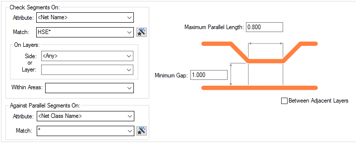
The Track Parallel Rules dialog is used to specify the length and minimum gap between parallel track segments. Using the Attribute Name and Match Value pairs, you need to specify two sets of tracks which will be checked against each other.
The general rule matching mechanism is described here.
Shortcuts
Menu: Setup
Default Keys: T
Command: Technology
Locating this option
Available from: Setup menu > Technology option > Rules - High Speed - Track Parallel page
Using the Track Parallel Segments Rules dialog
On selection, the Technology dialog opens, select Track Parallel Segments. The existing Track Parallel Segments Rules for the Technology being used will be presented.

Navigation
The buttons to the right side of the dialog are used to navigate the grid, the general common buttons are detailed on the Technology Navigation page.
Using the editing pane

Rule Significance
The only significance of the order of the rules is which rule will be tested first, if that rule fails, no further rules are checked. I think it would be normal to have the lowest minimum gap first.
Check Segments On
Attribute
Specify the first net based item; Attribute Name and Match Value pair for the Parallel segment rule to check against. This can be explicit or the name can use a wildcard match.
On Layers
You can decide whether to run the rule on a specific Side: or Layer: selected from the drop down
list selections provided, such as Top, Bottom, all Inner or both Outer (Top
& Bottom) electrical layers. Alternatively, you can specify a specific layer name, or a
wildcard matching string. (So ‘ground *’ would match
layers ‘ground 1’ and ‘ground 2’). The Wildcard Wizard is enabled
using the small icon next to the Match Value entry. If you wish to run the rule on all layers, either
define Side as
Within Areas
If you have any Areas defined in the design, a rule can be defined for a specific named area. Rules can be defined for any combination of Layers and Areas, as required. Similarly, a wildcard string can be defined to match areas. The matching areas must be marked as a Rule Override Area.
Against Parallel Segments On
Specify a second Attribute Name and Match Value pair for the Parallel segment rule to check against. for example, you could define a Parallel Rule between Signal nets and Power nets (in which case the match criteria would be different), or between all Power nets and all other Power nets (in which case the match criteria would be identical).
Parallel Track Segments
Maximum Parallel Length
The maximum distance parallel tracks can run before it is considered an error. The parallel length is cumulative, so a pair of tracks which turn a corner together are still considered parallel.
Minimum Gap Between
The minimum distance before segments are considered parallel. A very large gap may cause a performance issue when checking this rule. You can define multiple rules with increasing Minimum Gaps which allows you to check using a larger Maximum Parallel Length at increasing distances.
For a given rule, a pair of tracks within the minimum gap is checked for parallel sections, there is an error if the total parallel length with that gap exceeds the Maximum Parallel Length defined.
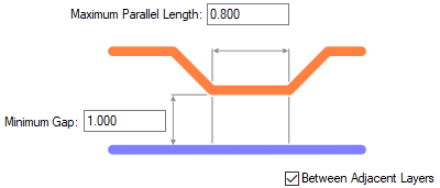
Note: When checking segments on the same layer, the gap is from edge to edge. When checking segments on adjacent layers, the gap is centreline to centreline, so a minimum gap of 0 would report only tracks with centrelines running directly on top of each other.
Between Adjacent Layers

Check the Between Adjacent Layers button to specify that the matched value rule is against track segments that appear on an adjacent electrical layer; the next electrical layer above or below. Adjacent layers are determined by the layer order defined in the technology. This gives you a check for parallel tracks running underneath.
Cascading Rules
For a cascaded set, there is a reasonable in-built assumption that a larger gap will allow greater parallel length. For the cascaded rules, the Max Parallel Length will include the length at the narrower gaps as well, so the Max Parallel Lengths must always be increasing.
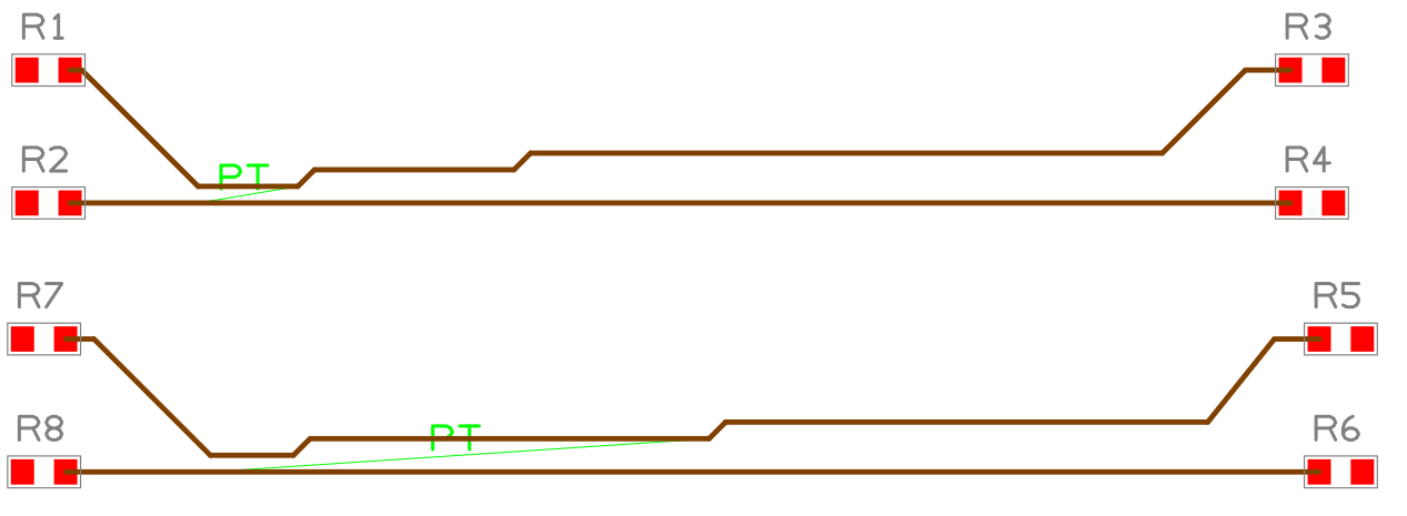
When using cascading rules on the same net, the first rule only applies to the closest sections, the next rule applies to the next and so on. The final rule applies to all parallel sections on the whole track.
The example below demonstrates a simple cascade rule using three rules on two nets. The rules for each net are shown from the Technology dialog:

These rules are applied to our PCB example where errors are displayed:

Reports
When DRC is run, a detailed report will be displayed highlighting track segments in error using the PT marker.
	Parallel Track Distance Exceeded (PT) Between (18900.0 19900.0) and (18750.0 19875.0). Layer 'Top'. Required 110.0 Actual 150.0
		Track Parallel Segments Rules: <Net Name>=CLK - <Net Name>=* on All Layer Side
		Min Gap: 17.0  Max Parallel Length: 110.0

	Parallel Track Distance Exceeded (PT) Between (19500.0 19375.0) and (18750.0 19325.0). Layer 'Top'. Required 461.0 Actual 725.0
		Track Parallel Segments Rules: <Net Name>=RST - <Net Name>=* on All Layer Side
		Min Gap: 42.0  Max Parallel Length: 461.0

	Total:
		 2 Parallel Track Distance Exceeded (PT)

	Checking took 0.204 Seconds
	Number of errors found : 2
Export and Import CSV
Use the Export CSV button to export the data in your PCB design into a CSV format file. Using the Export CSV option will provide you with a formatted template ready for you to edit in your own data.
Use the Import CSV button to import data back into the PCB design using a CSV format file.
The data in the file represents a spreadsheet of dialog contents with the data headings along the top row.
Units
The Units button allows you to locally switch between Metric and Imperial units whilst in this dialog. Once the dialog is closed, the units revert back to the original design units. If switching to different units to the design units, the value typed will be converted when you next enter this page.
Related Topics
Technology Overview | Using Dialog Grids | Design Rule Check | Export CSV | Import CSV