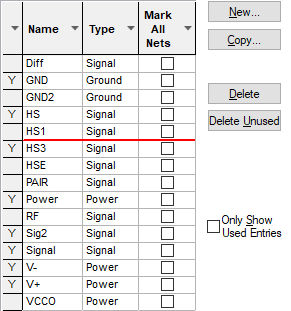
Net Classes provide a means of grouping Nets.
You can use them to associate attributes with the nets which use a Net Class. You can associate a Net Name with a Net Class in the Net Names dialog.
You can use the Net Class Name to associate nets with rules defined in the Technology.
The Net Class is passed forward using Translate To PCB from the Schematic design, so the track styles of special signals (such as power nets) can be controlled from the Schematic.
Shortcuts
Menu: Setup
Default Keys: T
Command: Technology
Locating this option
Available from: Setup menu > Technology > Net Classes tab
Using the dialog
On selection, the Technology dialog opens, select Net Classes. The existing Net Classes for the Technology being used will be presented.

By right clicking in the grid, you can select Advanced View from the context menu. This opens the grid to expose attribute rules and matches:

Navigation
The buttons to the right side of the dialog are used to navigate the grid, the general common buttons are detailed on the Technology Navigation page.
Using the editing pane

Net Class Name
Define the Net Class Name required. Rules and Attributes can be define for net name.
Type
The Type will be selected from one of three types available - Signal, Power or Ground. Some reports and functions have the option to treat Power or Ground nets differently to Signal nets. This is useful because Power or Ground nets are often distributed through planes or distribution lines. You can predefine part pins and schematic symbols explicitly for use with Power or Ground nets.
Mark All Nets As One
Enabling Mark All Nets As One will cause all nets using this net class to be marked at the same time. By default, this will not be enabled. In some cases a Signal Path might be more appropriate.
Rules and Attributes
Any rules or Attributes defined for the Differential Pair or Differential Pair Chains will be show here. Use the Add, Edit and Delete buttons to add or edit extra rules or attributes. More information about editing these fields can be found on the Rules and Attributes help page.
Units
The Units button allows you to locally switch between Metric and Imperial units whilst in this dialog. Once the dialog is closed, the units revert back to the original design units. If switching to different units to the design units, the value typed will be converted when you next enter this page.
Related Topics
Technology Overview | Net Name | Net Styles | Translate to PCB | Using Dialog Grids