Use this to place bond pads around a shape when creating a Footprint symbol that uses Bond Pads. This option is only available if you have the chip Packaging Toolkit feature in your license.
Shortcuts
Default Keys: None
Default Menu: Tools
Command: Place Bond Pads
Locating this option
Available from: Tools menu > Place Bond Pads option
How To Use Place Bond Pads
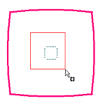
Firstly, you must add a shape to the footprint to which the bond pads will be placed. This can be a permanent shape like a placement outline or it can be a temporary shape that you will remove afterwards.
With the Place Bond Pads option selected from the Tools menu, you must select a shape as the ‘guide’ around which the pads are to be placed. This can be any type of shape (area, doc shape or copper).

You can then select bond pads (or the corresponding die pads).

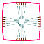
The pads are then placed on the nearest suitable point on the shape, using the current grid setting.

When placing the pads, the Auto Rotate setting is used to determine whether to spin the bond pads so they lie exactly along the wire, or at the nearest 90-degree angle to the wire.