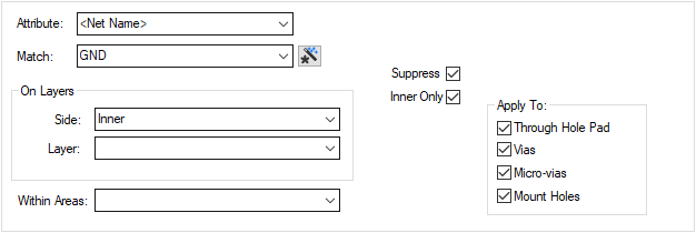
The Suppress Land Rules dialog is used to specify which lands of unconnected pads are suppressed and on which layers.
The general rule matching mechanism is described here.
Shortcuts
Menu: Setup
Default Keys: T
Command: Technology
Locating this option
Available from: Setup menu > Technology > Rules - DFM/DFT - Suppress Lands tab
Using the dialog
On selection, the Technology dialog opens, select Rules - DFM/DFT - Suppress Lands. The existing Suppress Land Rules for the Technology being used will be presented.

Navigation
The buttons to the right side of the dialog are used to navigate the grid, the general common buttons are detailed on the Technology Navigation page.
The Up and Down buttons are used to position and move the selected rule in the grid. These are useful to move rules around especially when trying to position them for better visibility in the design (the order looking down the list is how they will be presented in the design).
Using the editing pane

The following describes each parameter defined in the dialog:
The appropriate rule is found for each net or pad by working down the list of rules until the first match is found. Hence, the order of the rules is important. A match is when the specified Attribute Name and Match Value match attributes of a net or pad. So the pad (or net) must have the given attribute, and it’s value must wildcard match the value.
On Side:, Layer: & Area
You can also restrict the rule to apply only to pads on the specified Side or Layer; or within the matching named area.
You must also specify if the rule applies to ![]()
If you have any Areas defined in the design, a rule can be defined for a specific named area. Rules can be defined for any combination of Layers and Areas, as required. Similarly, a wildcard string can be defined to match areas. The matching areas must be marked as a Style Override Area and must have a name so they can be identified.
Suppress
This would normally be checked, unless you wanted create a rule which prevents suppression for specific items, which would otherwise match a lower rule.
There is an option in the design rules to determine what shape the spacing checks will use. This will either be the drill hole shape (if present), or the original pad shape that would have been plotted.
Micro-vias will not be suppressed on their Entry Pad or Stop Pad layers.
Inner Only
There is a separate option to override the land suppression when on the Inner Only (not top or bottom) layers of the span. A land is unconnected if there is no track to it on that layer and it is not contained in a template of the same net, on that layer. The land is not drawn and will not be plotted.
Applies To
You can choose to suppress unconnected lands on Through Hole Pads, Vias , Micro-vias or through-hole Mounting Holes on an electrical layer.
Export and Import CSV
Use the Export CSV button to export the data in your PCB design into a CSV format file. Using the Export CSV option will provide you with a formatted template ready for you to edit in your own data.
Use the Import CSV button to import data back into the PCB design using a CSV format file.
The data in the file represents a spreadsheet of dialog contents with the data headings along the top row.
Units
The Units button allows you to locally switch between Metric and Imperial units whilst in this dialog. Once the dialog is closed, the units revert back to the original design units. If switching to different units to the design units, the value typed will be converted when you next enter this page.
Related Topics
Technology Overview | Using Dialog Grids | Layers Dialog | Layer Class Dialog | Export CSV | Import CSV