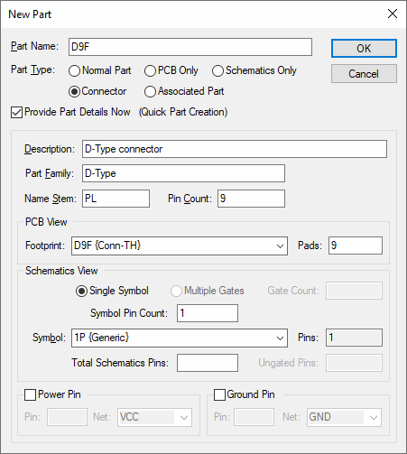
This dialog is displayed when you start creating a new part, either from the Parts tab of the Libraries dialog, or from the New dialog.
Locating this option
Available from: Library Manager option > Edit button > Parts tab > New option
Available from: File menu > New option > Designs option > Part
How to Use This Dialog

Part Name: enter the name by which this part will be referenced.
Part Type: enter the type of part required.
- A Normal Part is intended for use in both Schematics and PCB designs.
- PCB Only is for use in the PCB editor and has not Schematic Symbols on it. It can be converted to add a Schematic symbol at any time though so it can be used in both editors.
- Schematic Only is for use in the Schematic editor and has not footprint on it. It can be converted to add a footprint at any time though so it can be used in both editors.
- A Connector is a special part that allows you to place each connector pin separately in the Schematics but by only defining one Schematic symbol for use on every pin.
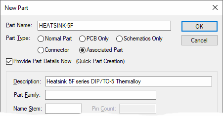
- Associated Parts are added to other Parts or Designs to define items, which are not physically placed in the Schematic or PCB design, but which should appear in the netlist. These are useful for adding screws, heat sinks, sockets, etc.
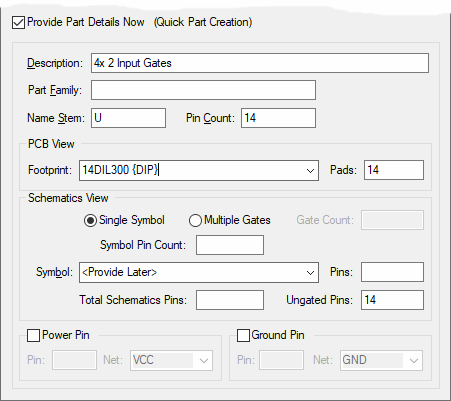
Select the Provide Part Details Now box to specify that you wish to enter the details of the part now. The lower part of the dialog (show below) will be displayed to enable entry of part details (footprint name, symbol name etc) for fast part generation. Leave this box unchecked to create a blank part that can have its details entered later using the Parts Editor.

- Description: an optional description to help you identify this part later, for example on a printed ‘Bill of Materials’.
- Part Family: can be used as a way of linking together related parts for easier browsing.
- Name Stem: specifies the text to be used for the first part of the component name when this part is used in a design.
- Pin Count: specifies the number of pins on the component itself, and hence the number of pads on the PCB footprint. Specifying this value here makes it easier for the application to help you locate suitable footprint items.
Both the PCB View (for PCB Footprints and Schematic View (for the Schematic
symbols) can be defined now or, by leaving as
The Power Pin and Ground Pin check boxes enable you to define predefined net names for a power
and ground pin on your part. Symbols) can be defined now or, by leaving as
Pressing OK will finish this part and the details defined will be checked for correctness. Your new part will then be opened for editing in the Parts Editor.
Creating a Connector Part

Connector parts are similar to ‘normal’ parts, but have a simplified structure as they do not need all the Schematic gate information that would be required for a normal part.
To create a new Connector part, select the “Connector” radio button. The “Symbol” control on the dialog will become enabled, allowing you to select the symbol to use for each connector pin on the Schematic drawing.
Creating an Associated Part

Associated parts are parts that do not have any pins, footprints or symbol information. They are used to associate to normal parts, or directly to PCB designs, in order to add additional parts required when building the board. For example, a heatsink required for a specific part.
To create a new Associated part, select the Associated Part radio button.