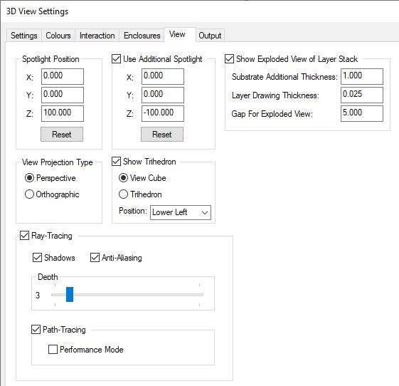
The View dialog allows you to adjust parameters surrounding the visual representation of any 3D Views for STEP.
Shortcuts
Default Keys: None
Default Menu: 3D Design
Command: 3D Settings View
Locating this option
Available from: (design) 3D Design menu > 3D Settings> View tab
Available from: (3D Viewer) 3D Design menu > 3D Settings> View tab
Using the dialog
On selection, any existing settings for view will be presented.
The views that utilise any form of 3D visualisation are customisable. Using this dialog you are able to define the 3D View representation.

Spotlight Position
The Spotlight Position controls show the current position of the directional spotlight used in the 3D Viewer. The default position of X=0, Y=0, Z=100 will directs the light from above the board the at position of the Coordinate System Origin, but can be adjusted to an alternative setting if preferred. For example, a change to X=0, Y=0, Z=-100 will shine the spotlight from below the board instead of above. Use the Reset button to reset the spotlight to the default position.
Use Additional Spotlight
By the checking this box, you can add an Additional Spotlight to the 3D Viewer to provide more contrast. Use the Reset button to reset the spotlight to the default position.
Show Exploded View Of Layer Stack
The lower half of the dialog contains settings relating to the exploded view representation of a PCB design.
Note: with this mode enabled, you cannot use or view Board Bend Lines.
Checking the Show Exploded View of Layer Stack option switches on the exploded view and allows access to the exploded view options contained below.
Substrate Additional Thickness : this is the thickness of the substrate layers in the view which represent the board, the thickness specified here is added to any thickness defined in the layer stack. So if the layer thicknesses are specified in the technology, you may want to set the value here to 0.
Layer Drawing Thickness : this is the thickness allowed for each layer of information (copper, silkscreen, etc). This value should not be set too small (or to zero), otherwise each 3D layer will occupy virtually the same ‘vertical’ location and will ‘bury’ itself into the substrate. The end result would be that tracks and other items would disappear from the 3D picture.
Gap For Exploded View : this is the spacing to allow between substrates when drawing the exploded view of a multi-layer board.
More information about the Exploded View is provided on the Exploded View help page.
View Projection Type
The View Projection Type determines the visualisation of the entire 3D view, detailed below are the two available types.
Perspective: has depth by utilising a vanishing point giving straight lines the illusion of merging in the distance. Gives a more realistic look to models in the 3D View.
Orthographic: is a fixed depth. All lines appear to have the same length, and is commonly used for measuring lines to determine they are an exact match when opposite each other to prevent uneven measurements.
Note: by default Pulsonix will use the Perspective view in all 3D Views, including model previews for footprints and enclosures.
Show Trihedron
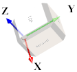
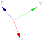
The 3D axis in the 3D Viewer and Position STEP Model dialogs can be viewed as a Trihedron Cube or as Arrows. The Position can also be changed to one of four corner positions within the preview window using the predefined dialog settings on the drop-down list.
The Trihedron Cube is displayed like this:

The Trihedron Arrow is displayed like this:

Ray-Tracing
Ray-Tracing is an accurate technique for modelling real-time lighting, because it follows the natural path for how light can propagate around a scene, such as a PCB design in the Pulsonix 3D Viewer.
Shadows
Enables/Disables shadows rendering
Anti-Aliasing
Enables/Disables adaptive anti-aliasing
Depth
The number of times a ray can bounce or interact with surfaces in the scene before it is terminated.
Path Tracing
Path-Tracing is a more modern method of modelling real-time dynamic lighting in a scene but does put more of a demand on the rendering hardware (GPU).
Performance Mode
This option is a less GPU intensive version of path tracing, to be used if the default version is causing performance issues.
Related Topics
3D Settings | 3D Colours | 3D Interaction | 3D Enclosures | 3D Output | 3D Layers | STEP Library