Use this dialog to create and list all the Differential Pairs defined in the design. You can also create and edit Differential Pair Chains using this dialog.
Shortcuts
Menu: Setup
Default Keys: T
Command: Technology
Command: Create Differential Pair
Locating this option
Available from: Setup menu > Technology option > Differential Pairs tab
Using the Differential Pairs dialog
On selection, the Technology dialog opens, select Differential Pairs . The existing Differential Pairs for the Technology being used will be presented.
By selecting items on two appropriate nets, you can use the Create Differential Pair command from the context menu, to populate the dialog with the correct nets.
A Differential Pair is a pair of pins on two different nets which should be routed together. The pair may have rules associated with it which define how close the tracks should be and how much they are allowed to differ in length. These rules can be checked by the Design Rules Checker.

Note: the above rules window is not fully expanded and does not show the full rules displayed. See below for more details about the rules.
Navigation
The buttons to the right side of the dialog are used to navigate the grid, the general common buttons are detailed on the Technology Navigation page.
New Chain
The New Chain button is used to create new Differential Pair Chains. These will be based on two or more Differential Pairs.
Creating Chains From Rules
You can create rules in a number of ways; using this dialog, using the New button and defining the Differential Pair or by clicking Create Pairs From Rules… button. This opens up a dialog displaying automatically generated differential pairs using rules. these rules are defined on the Differential Pairs Nets rules dialog.
Using the editing pane

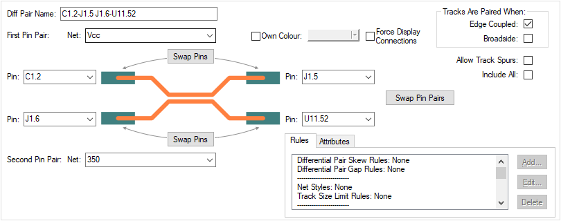
Diff Pair Name
Use the New button to create a new Differential Pair.
Note: You can define the pin pairs by firstly selecting the two connections that define the pairs in the PCB design. Then, using New will automatically setup the two sets of pins in the dialog. Ensure that the correct pins are selected.
The Diff Pair Name can be a unique name of your choice. By default, the name will be created using the two pairs of pins and their component reference names. The default name will reflect changes to the component names. If you type a name, you will need to ensure it remains correct. You can return to the default name by deleting the name.
Use the Rename To Match Rule button if available to apply the name specified by rules created using the Differential Pair Net Rules dialog. This will be unavailable if there are no Differential Pair Net Rules matching this pair, and will be disabled if there are rules that match the current name.
First Pin Pair and Second Pin Pair
If creating a new Diff Pair without pre-selecting connections in the design, use the First Pin Pair and Second Pin Pair drop down list boxes to select the Net name from the design. You cannot change the pins in the grid.
The Pin drop down list can be used if you wish to change the pin.
Use the Swap Pins buttons to swap the start and end Pin with each other.
Use the Swap Pin Pairs buttons is used to swap the top connection with the bottom one.
Own Colour
Use Own Colour enables you to highlight the differential pair path between the pairs of pins in it’s own colour.
Force Display Connections
When Connections are switched off in the design, selecting the Force Display Connections check box will force this differential pair to be visible.
Tracks Are Paired When
You can define how the tracks are paired. Edge Coupled are the usual differential pairs, the edges of the two tracks separated by the specified gap. Broadside are paired vertically, the tracks laid on top of each other on different layers. It is possible to allow both types of pairing on a differential pair.
For Broadside only coupling, the gap can still be provided and will be used for the minimum separation of the tracks when they are on the same layer, for example when routing out of surface mounted pads but this will not contribute to the % paired.
Allow Track Spurs
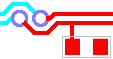
Normally, the path between the pins in a differential pair should be without any spurs or branches to other pads, vias, etc. Checking the Allow Track Spurs option will allow spurs from the track path. These spurs must not have any further spurs or branches and should be terminated on a pad, via or testpoint. These will be checked as part of the Differential Pair Design Rule Check and in the Differential Pair report.

Include All
Normally pins are not included in the path between the pins at the ends of the differential pair, but sometimes this is required. Checking the Include All box will instruct Optimise Nets to connect to any extra pins on the net that are in this path and not assigned to other differential pairs, allowing you to route them into the path without a differential pair error.
Expanded Rules
When this dialog is fully expanded, the rules used within the Differential Pairs are displayed. In our example below, we have moved the window across using the slider so that the rules are visible.

Rules and Attributes
Differential Pairs can have attributes, this is primarily so that you can make them match rules. Suitable
rules can also use the in-built
The Rules tab gives you a summary of the rules which currently match the selected differential pair. More information about editing these fields can be found on the Rules and Attributes help page.
Export and Import CSV
Use the Export CSV button to export the data in your PCB design into a CSV format file. Using the Export CSV option will provide you with a formatted template ready for you to edit in your own data.
Use the Import CSV button to import data back into the PCB design using a CSV format file.
The data in the file represents a spreadsheet of dialog contents with the data headings along the top row.
Units
The Units button allows you to locally switch between Metric and Imperial units whilst in this dialog. Once the dialog is closed, the units revert back to the original design units. If switching to different units to the design units, the value typed will be converted when you next enter this page.
Differential Pairs in the Rules Spreadsheet
The Rules Spreadsheet provides information about the differential pairs in the design. This displays the rules and actual lengths as they are edited in the design. This is presented to you in a dockable modeless bar.
Related Topics
Technology Overview | Differential Pairs Overview | Differential Pair Net Rules | Rules and Attributes | Create Pairs From Rules Dialog | Differential Pair Chains | Differential Pair Gap Rules | Differential Pair Skew Rules | Differential Pairs Spreadsheet | Design Rule Check | Export CSV | Import CSV