This page describes the various requirements and checks to carry out if you wish to use the board bending option in the 3D Viewer.
When to use Board Origins and Flexi Bend Lines
There are two items that effectively do a similar function but are used for two slightly different purposes:
- Board Origins - these are used to add origins to regular boards that are not flexi but require positioning in the 3D Preview.
- Flexi Bend Lines - these are used when you wish to fold flexi boards. The lines added indicate where the fold will be plus the angle and bend radius.
Setup and Usage
There are a few items to set up and review before board bending can be completed.
Setting up Layers
You will need to ensure the correct Layers and Layer Span are in your design. An example of a simple Flexi-Rigid layer stack is in the Layer Flexi-Rigid example technology.
Inner electrical layers will need to be created for the flexi span, shown below and named as Flexi layers (Flexi Top and Flexi Bottom), along with supporting documentation layers if required.
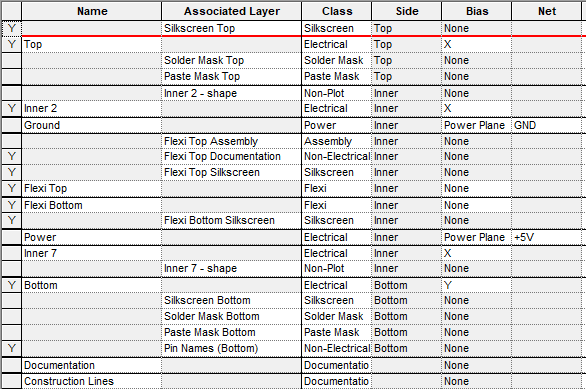
An appropriate Layer Span across these layers will need to be created, show here named Flexi Layers.

Adding Boards and Board Types
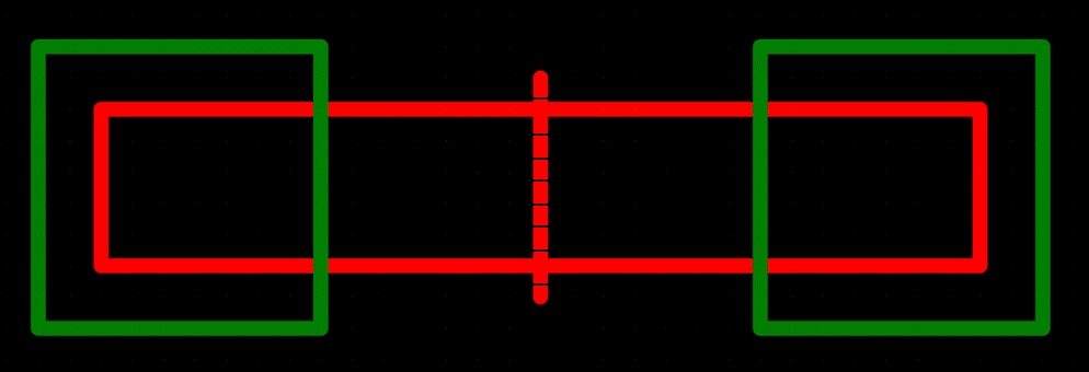
Create your required boards with the flexi board intersecting other boards so they are connected to each other. Change the Layer Span of the flexi board to be on your flexi layer span. For example (shown below with the green outlines being board and red as flexi board):
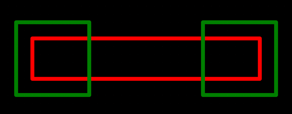
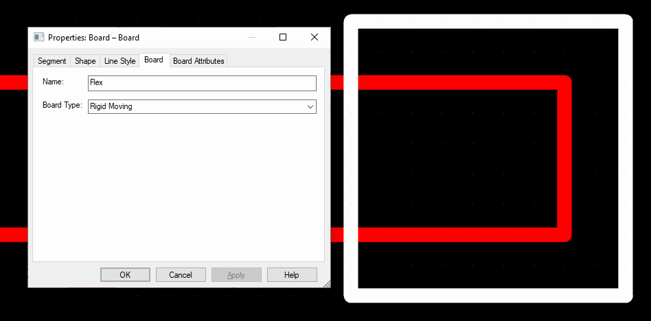
Flexi board folding works by looking at the relationship between board types, and calculates the fold and affected transformations dependent on this. Therefore, the board types need to be initially set up correctly using Board Properties. There are three board types in Pulsonix:
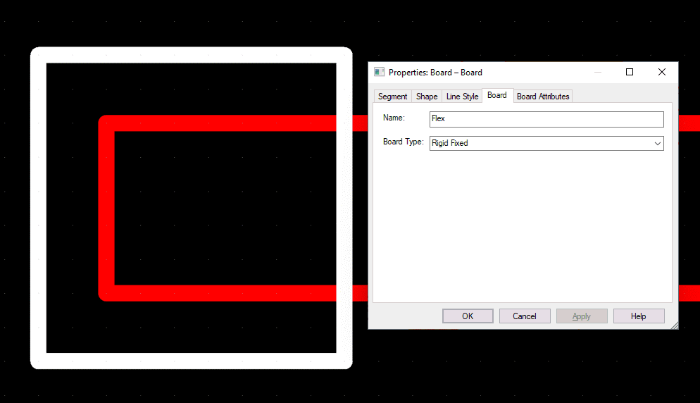
- Rigid Fixed a board that is fixed in position and will not be folded or transformed.
- Rigid Moving a board that will move based on folding flexi boards, but will not be folded.
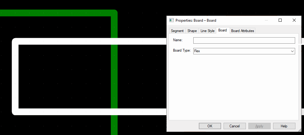
- Flex a board that will be folded, and can also be transformed based on other folding flexi boards.
For a flexi board to be folded, it must be attached to (intersecting with) a Rigid Fixed board (either directly, or attached to a moving board which is attached to a flexi board which is attached to a fixed board etc.), and can optionally be attached to one or more Rigid Moving boards. Attaching to multiple Rigid fixed boards may produce unexpected results.
To change the Board Type of an inserted board, select the board(s) and click Properties on the context menu, and go to the Board tab.
Below illustrates an example of each Board Type:
Rigid Fixed Board
Flexi Board
Rigid Moving Board
Adding Bend Lines
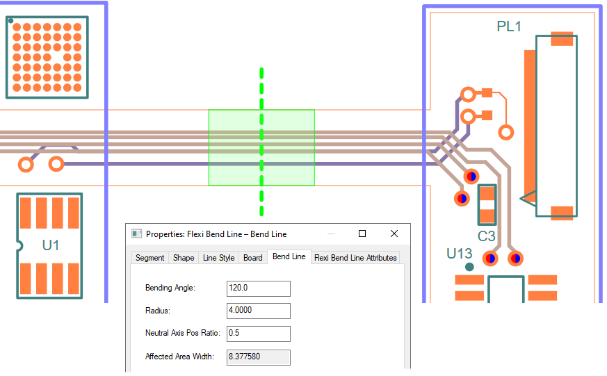
Bend lines are used to define the section of a flexi board that will folded. A bend line is a single segment that cuts through the flexi board, accompanied by two other lines (called the Affected Area) offset from the main line. These two lines show the extents of the fold area, and their position are dependent on the Angle and Radius values that are you can define on the bend line.
To add a bend line, click on a flexi board, right click to open the context menu, and click the Insert Flexi Bend Line option (this option is not available on rigid fixed and rigid moving boards). To start adding the bend line, click outside the board and draw the segment so that it slices through the board, and end the segment outside the board. The result should look something like this:
Bend Line Properties
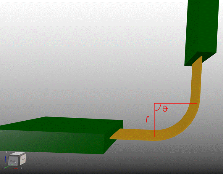
The bend region is defined using an Angle and Radius.
The Angle defines the angle at which the bend region will be folded - labelled as theta in the diagram below.
The Radius is defined as the distance away from the bend region that the centre point of the bend is located - labelled as r in the diagram below. The radius can be positive or negative, a positive value will fold the bend region in the positive Z direction, and a negative value will fold in the negative Z direction.
Altering the Angle and Radius will change the size of the bend region; which can be seeing visually when the offset bend lines move position, or numerically by looking at the Affected Area Width in Flexi Bend Line Properties. This denotes the current width of the bend region.
After setting up the Bending Angle and Radius, your design should look something like this:
3D Settings for Flexi Board Folding
There is a Flexi Board Folding section on the 3D Settings Interaction page accessed via the 3D Design menu. This defines how the folding will behave and its use of animation.
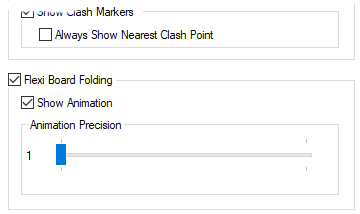
The Flexi Board Folding option defines whether or not the fold shapes will be calculated. If disabled, you will not be able to fold. The shapes required to fold are calculated during the initial generation of the 3D view, which can take a long time. If it is not required for the user then they can disable it to save time.
The Show Animation option will animate the board fold. When enabled, the fold shape generation time will increase, but folding in 3D Preview will now be animated. When disabled, performing the flexi fold will show the folded shapes instantly, similar to how the Fold Board option works.
The Animation Precision slider defines how smooth the animation will. The higher the precision, the smoother the animation, but it will cause longer 3D generation time.
Applying the Fold in the 3D Preview
Once the boards are set up correctly in the PCB, you can enter the 3D Viewer.
To perform the fold, use the Fold Flexi Boards option on the 3D Design menu. Using this option when flexi boards are already folded will unfold them using the same animation options applied in 3D Settings.
The Fold Flexi Boards option can be used alongside the Fold Board option.
Copy/Paste of Bend Lines
You can copy and paste Bend Lines. As bend lines require a board to function correctly, you are unable to paste a copied bend line if you have nothing currently selected.
If you have a bend line selected when pasting, it will copy the values of the bend angle and bend radius to the newly pasted bend line, and it will be linked to the same board that the currently selected bend line is linked to.
If you have a board currently selected, pasting a bend line will link the new bend line to that board, but will not copy any angle or radius values.
Outputting STEP (or STL)
Using the Write STEP File option on the 3D Design menu in the 3D Viewer while the design is folded will output the design as folded to the STEP file.
Illegal Items
Some items are not allowed in bend regions. This will be shown in the 3D viewer with a Bend Region Clash label being shown and the offending objects highlighted in red. If there are clashes, that specific fold will not be performed, but all others will be. Items not allowed in bend regions include:
- Components
- Boards
- Other items may also not be allowed by your manufacturing process, such as Vias.
Design Rules Checking
There is a dedicated check within the DRC dialog for flexi boards. The Flexi Bend Regions check ensures specific rules are followed:
- Flexi bend lines without a bend region. This could report errors where the defined Angle or Radius is zero, or because the bend region is too large for the section of board where the bend line currently is. If this is the case when the 3D Viewer is launched, this bend will be ignored.
- Flexi bend regions intersecting with other flexi bend regions. Two regions intersecting will cause one region to bend but not the other when in the 3D Viewer.
- Flexi bend regions intersecting with boards. If the region intersects with a board, then it will cause an illegal bend, and so will be ignored.
- Flexi board folding works by folding flexi boards and transforming Rigid Moving boards around a single Rigid Fixed board. If another rigid fixed board exists in the collection of boards being folded, then it will cause folding that is not intended (as the fold direction is determined by its relative position in comparison to the fixed board). The check will look for multiple fixed boards in a collection of boards.
These rules are explained in detail in the online help under DRC.
Board bending cannot be shown when the board is being viewed as an Exploded view or as a Single Entity.
Related Topics
STEP Overview | Output STEP | 3D Viewer | Board Origins | Flexi Bend Lines | 3D Settings Interaction | 3D Viewer