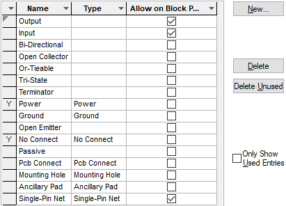
This dialog lists all the names of the pin types that are available in this design. New pin types can be added in this dialog.
Pin types are added to pins when creating Parts and Blocks. They are used to check the connectivity using the rules defined in the technology. A pin can have its type overridden in the schematic design.
Shortcuts
Menu: Setup
Default Keys: T
Command: Technology
Locating this option
Available from: Setup menu > Technology option > Naming > Pin Types tab
How To Use Technology - Pin Types
On selection, the Technology dialog opens, select the Pin Types tab.

A ‘Y’ in the first column indicates that the Pin Type is used in the design. Once used, it cannot be deleted.
Navigation
Press the New button to add a new entry to the list. To edit an existing entry, select it, the row will be underlined with a red line. The information can then be edited in the editing pane below it.
Remove items from the list by selecting it and pressing the Delete button. Use Delete unused to remove any styles in the list that are not currently used in the design. Used styles cannot be deleted.
Use the Only Show Used Entries check box to only show Pin Types that have been used in the design.
Using the editing pane

Name
Each pin type must have a unique name, this is what is used to match pin types with the rules which apply to them.
Type
There are some special types which have a meaning to the application:
Ground & Power, these help the application to connect a ground or power pin to a net of the appropriate type (see Net Classes).
No Connect defines a pin as not connectable, it is an error to connect to a pin of this type.
Pcb Connect defines an ungated pin as connected in the PCB, it is not an error for the ungated pin to not be connected in the Schematic. This would typically be used on a pin which is connected through the internal connectivity of the footprint, and is of no concern to the Schematic designer. If the pin is connected in the Schematic, then it must be connected to the same net in the PCB.
Ancillary Pad defines a pad which does not contribute to the overall Part Pin Count. In all other respects it is a normal part pin. It has a pin name, can appear on a schematic symbol, and requires a pad in the footprint. This might be used to define a belly pad for example, used on a surface mount device with a thermal connection.
Mounting Hole defines a pad which does not contribute to the overall Part Pin Count.
Also, in a PCB design, it is treated like a Mounting Hole for Rule checking purposes. In all other respects it is a normal Part Pin. It has a Pin Name, can appear on a Schematic Symbol, and requires a pad in the footprint, (the footprint will therefore have more pads than the Part Pin Count). This means it can be shown on the Schematic Symbol and design also, and be connected to with a Net Name.
The Single-Pin Net type enables you to distinguish between pins specifically marked as single pin nets and those accidentally left as single pin nets.
Allow on Block Port
Check the box to allow the pin type on a block port. A block port can use different rules to a normal pin.
Related Topics
Pin Type Pair Rules | Electrical Rules Check | Part Edit - Pins | Properties - Block Ports