Use this to define the type of SPICE device that the selected component or library Part represents.
Shortcuts
Default Keys: None
Default Menu: Simulation
Command: Edit Spice Value/Model
How To Define The Spice Type
There are two ways of changing a Part’s SPICE type, either locally on a Schematic Component, or directly on a Part in a Library.
In a Schematic Design, select the Component that you wish to change. Use the Edit Spice Type option from the Simulation menu.
From a Parts Library edit the required Part. Press the Edit Spice button on the Details tab.
If the Part is heterogeneous (contains more than one type of symbol) then a special dialog is used to supply Spice details for each symbol type. This dialog is dealt with in the section on Heterogeneous Parts below.
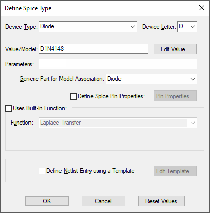
For other parts the following dialog will be displayed:

Device Type
If not using a built-in device, choose the required SPICE type by selecting from the Device Type list or from the Device Letter list.
Value/Model and Parameters
When the device type has been set up, click on the Edit Value button to change the value/model name and parameters using the appropriate Edit Spice Value/Model dialog.
Generic Part
If the device type requires a SPICE model or sub-circuit name, the Generic Part field will be available.
Edit the Generic Part entry to specify the Part name that is used to associate with the Simulator SPICE models. In the example shown the part is called “Diode”, so it is the generic part. In other cases the part could be more specific to a particular Diode model, e.g a part called D1N4148 could be created for transferring to the correct PCB device for that model. This would still refer to the generic Part “Diode”.
Spice Pin Properties
Normally the pins are included to the SPICE netlist if they exist on the symbol and they are output in the symbol pin sequence order. If you wish to change the order the pins are output, include ungated pins, remove gate pins or define XSPICE connections, then check the Define Spice Pin Properties box and use the Pin Properties button to set it up.
Template
The SPICE netlist entry for this Part will be automatically generated when a Simulation is run. If you wish to replace this entry with your own SPICE netlist entry, tick this checkbox and use Edit Template to define the netlist entry template.
Reset Values
Resets all values back to those of the original Part in the Library.
Built-in Function
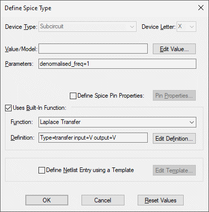
Pulsonix contains many built-in XSPICE devices and sub-circuits that have their own specific Edit Value dialogs to make it easier for you to set up the device.
Most of these also have their netlist entry defined using a Spice template. This template can be edited if, for example, you wish to use alternative built-in parameters or sub-circuit naming conventions.
Some of these built-in devices have functional definitions that provide extra information to describe the function of the part. In this case the Definition field and Edit Definition button will appear. The definition field will contain parameters that define the function of the device, making it different from other devices using the same built-in function name. See Functional Modelling for more details of these devices.
For example, a Shift Register is a built-in device that has a definition containing the number of bits in the register. So a 4-bit shift register will be a different part using a different symbol from a 8-bit shift register.
Use Edit Definition to use a specific dialog to easily enter the correct definition on the part to match its symbol. In a schematic design when using Edit Spice Value/Model (or F7) on one of these devices, the same specific definition dialog will be displayed. Changing the definition of the part in a schematic design will replace the part with one from the library matching the new definition.
Built-in Function Example : Laplace Transfer

The definition for the Laplace Transfer function defines the Laplace type and the description of the input and output signal types. These map to different symbols.
In this case the Edit Definition button will bring up the Laplace Transfer dialog.
Heterogeneous Parts
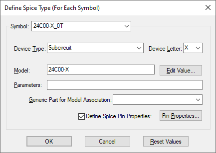
If the part consists of more than one type of symbol, we need to set up the Spice model for each of the symbol types. In this case the following dialog will be displayed:

Select each Symbol in turn and set up its Spice details. See the main section above for how to set up the controls shown on the dialog.
Heterogeneous parts can only have model or subcircuit names. You cannot use a template or special function for these parts.
Note: If using one of the symbols as a power gate, set its type to
Related Topics
Define Passive Device Value | Define Value | Edit Parameter | Edit Template | Functional Modelling | Laplace Transfer | Select Model | Spice Pin Properties | Part Details Define Spice