The Thermal Rules dialog is used to specify how pads and vias are connected to poured copper and power planes.
The general rule matching mechanism is described here.
Shortcuts
Menu: Setup
Default Keys: T
Command: Technology
Locating this option
Available from: Setup menu > Technology option > Rules - DFM/DFT - Thermal page
What are Thermal Spokes?
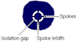
A thermal pad is used when a pad or via connects to a copper plane (either poured copper or a power plane). There are two competing constraints on such a connection. There needs to be an electrical connection. The pad also wants to be thermally isolated from the copper, otherwise heat is drawn from the pin through the copper, resulting in defective soldering. The solution is to isolate the pad by a given Isolation Gap and then connect it with Spokes of a given width. This is the top level description, however, other factors and rules can be defined depending on your requirements.

In general, you will probably use the same thermal pad rules for most nets, with just a few special exceptions which can be defined using the methods described here. For example, high power sub nets may need more spokes and a larger gap.
On a power planes, the spokes will be defined by cutting out the gaps in the copper around the spokes. With poured copper, the spoke is a piece of copper drawn with a rounded end. Where this rounded end would prevent the spoke from being added, the spoke may be defined with a square end instead.
Using the Thermal Rules dialog
On selection, the Technology dialog opens, select Thermal Rules. The existing Thermal Rules for the Technology being used will be presented.

Navigation
The buttons to the right side of the dialog are used to navigate the grid, the general common buttons are detailed on the Technology Navigation page.
Using the editing pane

The appropriate rule is found for each pad, template or net by working down the list of rules until the first
match is found. Hence, the order of the rules is important. A match is when the specified Attribute
Name and Match Value match attributes of a net or pad. So the pad (or net) must have the given
attribute, and it’s value must wildcard match the value.
In particular, you can match the inbuilt attributes
In general, you will probably use the same thermal pad rules for most nets, with just a few special exceptions which can be defined using the methods described here. For example, high power sub nets may need more spokes and a larger gap.
By adding an attribute to a specific pad, you can cause it to receive a different thermal shape to all the other pads on the same net.
By adding an attribute to a specific template, you can cause it to use different rules to pads within it, compared to other templates on the same net.
Applies To
You can make the rule specific to a type of pad (Any, Through Hole Pad (including Through Mounting Hole), Surface Mount Pad (including Surface Mounting Hole), Via (including Micro-via), Micro-via, Through Mounting Hole, Through Mounting Hole). Select the appropriate type in the list.
Note that the first matching rule will apply, so you need to define the rules in the correct order (e.g. a Micro-via rule should come before a Via rule).
Min Pad Size
If you want rules based on Minimum Pad Size (for the given pad type), the rule will match if this minimum pad size is exceeded.
On Layers
You must also specify if the rule applies to ![]()
Within Areas
If you have any Areas defined in the design, a rule can be defined for a specific named area. Rules can be defined for any combination of Layers and Areas, as required. Similarly, a wildcard string can be defined to match areas. The matching areas must be marked as a Style Override Area and must have a name so they can be identified.
Connect Type
The Connect Type selection allows you to choose how the thermal pad will be made. Choose from Isolated, Not Isolated and Thermal Pad:
- Isolated is used to completely remove any thermal connection to the pad. In this instance, you should ensure pads that should be connected to a power plane using and alternative connection method, such as a stub route.
- Not Isolated is used to make a solid plane connection with no thermal relief or isolation gap. Pads under this condition will be connected to plane.
- Thermal Pad will use the thermal rules specified in this dialog.
Enclosed Pads Only
Enclosed Pads Only - this option only applies to poured copper and not Templates on Power Plane layers.
For templates that will receive poured copper, with this option selected, it will only attempt to add spokes to pads which have the pad origin contained within the poured template. Otherwise, spokes may be added to pads which are close enough to the template (and the spoke may cross the edge of the template). The outline considered by this feature is the centre line of the template or further inside.
Note: For templates placed on Power Plane layers, the entire pad shape must be fully enclosed within the template before it receives any spokes. The Enclosed Pads Only check box has no effect on spokes for templates on Power Plane layers.
Image showing results when Enclosed Pads Only option not selected, the single pad at the bottom of the poured area has its pad origin outside of the template outline:

Design results once template is poured using this rule:

Image showing results when Enclosed Pads Only option selected:

Design results once template is poured using this rule shows the same pad at the bottom of the poured area with no spokes:

Orthogonal Spokes
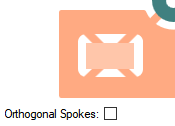
Orthogonal Spokes, when selected, this causes spokes to be orthogonal to the pad shape. This has no effect on round pads. On other shapes the spokes take the shortest distance across the gap from the same point where the angled spoke would have started. When unchecked, the spokes simply follow the line from the pad centre as shown below.


Isolation Gap
The Isolation Gap is the gap between the Pad and Copper connecting to the designated Net, given in design units. Note that you can override this value with an area to define the thermal gap for a specific pad.
Number Of Spokes
The Number Of Spokes connecting Pad to Copper, normally this will be 4, forming a cross. 0 spokes means that no spokes will be generated, you would have to add them yourself.
Minimum Spokes
The Minimum Spokes defines how many spokes are required to properly connect the pad. In Copper Pour, the pad will not be given any spokes if the minimum number cannot be added. The Plane Thermal Pad manufacturing check will give an error if a power plane pad cannot achieve this minimum number.
Try Alternative Rotation
Try Alternative Rotation, when checked will, in the case when the Minimum Spokes would not otherwise be achieved, try the spokes rotated by half the angle between the spokes. In particular, if you are using 4 spokes and the minimum number of spokes could not be legally added, it will try the 4 spokes rotated by another 45 degrees.
Rotate With Pad
Rotation With Pad, when checked will cause the spoke pattern to be rotated by the angle of the pad. So if a pad was at 25 degrees and the first spoke angle was 0 degrees, the first spoke would actually be a 0 degrees relative to the pad, but 25 degrees relative to the board as demonstrated below:

First Spoke Angle
The First Spoke Angle is in current angle units, 0 being horizontal and to the right. The other spokes will be evenly distributed relative to this first spoke.
These parameters are used both by Copper Pour, where the spokes are generated as copper segments, and post processing of power planes, where the gaps between the spokes are plotted. Both methods give the required results. Copper Pour will not generate a spoke if it would not connect fully, or would overshoot, the surrounding copper shape.
Spoke Style
The Spoke Style defines the connection width from Pad to Copper, given in design units. Copper Pour will use this style for the spokes of any thermal relief it creates. You can specify the style name, or the actual width.
How a thermal pad will be rendered
The following sequence is applied:
- If the pad properties defines Isolated or Not Isolated then no thermal pad is created.
- If the pad is contained within a Copper Template,
then the template may override the Net Class by having a value for the
property otherwise the Net Class is taken from the Net. - The list of Thermal Rules is scanned until a matching rule is found.
An Isolated Pad is isolated by the Copper to Pad spacing rule. A Not Isolated pad is fully connected directly to the copper.
If the Pad Style has a Spacing Shape defined for the current layer, then this will be used to determine the shape around the pad, instead of the actual pad land shape. This can be disabled by selecting the connection type Thermal Pad (ignoring Spacing Shape), this does not disable the Spacing Shape for any other spacing or rule checking process.
Export and Import CSV
Use the Export CSV button to export the data in your PCB design into a CSV format file. Using the Export CSV option will provide you with a formatted template ready for you to edit in your own data.
Use the Import CSV button to import data back into the PCB design using a CSV format file.
The data in the file represents a spreadsheet of dialog contents with the data headings along the top row.
Units
The Units button allows you to locally switch between Metric and Imperial units whilst in this dialog. Once the dialog is closed, the units revert back to the original design units. If switching to different units to the design units, the value typed will be converted when you next enter this page.
Related Topics
Technology Overview | Using Dialog Grids | Spacing Rules | Split Power Planes | Copper Pour | Post Processing | Design Rule Check | Export CSV | Import CSV