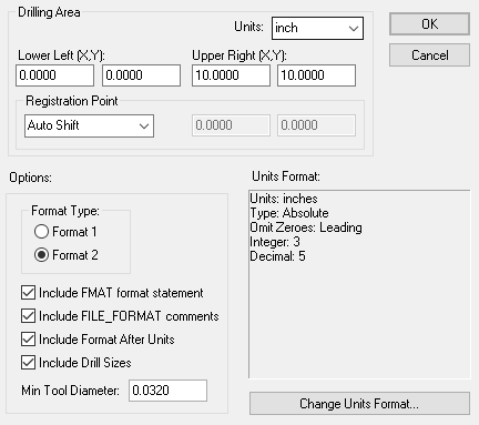
Use this dialog to set up the size of the drill table for which you are creating NC drill files.
Locating this option
Available from: Output menu > CAM Plots > Plot Settings > Setup - Excellon button
Using the dialog
The Excellon Setup dialog is accessed from the Plot Settings page of the Output CAM dialog.

This dialog is used to set up those Excellon output parameters that do not generally change from design to design. The values set up here are maintained between program sessions so you should only need to set them up once, to correspond to the device you are going to use.
Drilling Area
You should setup the Drilling Area, so that the plotting can determine if the plot will fit and it the plot should be shifted, rotated or scaled when appropriate.
Registration Point
The Registration Point is used for alignment with the Design Position defined in the Plot Wizard for each plot.
Format
This box shows the current settings for the options which are available to control the formatting of coordinates in plot files.
Change Format
Press this button to access the Change Format dialog, which allows you to modify the settings shown in the “Format” box.
Options
Choose Format 1 and Format 2 style of the Excellon output (unless you are using an old machine, Format 2 is recommended). Include FMAT format statement causes the format name to be added to the header in the file, best to add this unless you have a reason not to. Include Drill Sizes if checked, the output file will include an embedded table of drill sizes, again best to include this unless you have a reason not to.
Include FMAT format statement includes a statement, at the start of the file, of the form FMAT,2.
Include FILE_FORMAT comments includes some comments, at the start of the file, of the form ;FILE_FORMAT=2:5 (where 2:5 is the integer:decimal places format), ,INC is you are using incremental, and ,LZ is you are using leading zeros. You also get a comment of the form ;TYPE=PLATED or ;TYPE=UNPLATED when appropriate.
Include Format after Units includes, LZ (for leading zeros) or TZ (for trailing zeros) followed by the number format shown as 00.00000 for 2.5 (e.g. METRIC,LZ,00.00000). This is only relevant if you are using leading or trailing zeros.
Min Tool Diameter gives the smallest valid tool diameter. This is used to route custom shapes, no attempt is made to shrink these shapes, so it should be as small as possible.
This is very useful for the output of Pad Slots that have special or intricate shapes. This option defines the smallest valid tool diameter that will be used for these shapes. These would be shapes that are not regular slots that can be milled using a standard drill. When used to route custom shapes, no attempt is made to shrink these shapes so the drill should be as small as possible and in accordance with what your manufacturer can mill.
Output of drill holes and shapes
Excellon data is used to drive drilling or milling machines. Round holes can obviously be drilled, but non round holes must be milled, by cutting around the outline. If you output a shape (such as a board outline), the shape will be milled using a tool of the same width as the line style. Pad style holes do not have a style width specified, oval (finger) shaped holes are milled using a single cut using a drill bit of the appropriate width. Similarly, rounded rectangles will be cut using a drill bit with a radius the same as the rounded corners. Other shapes will be literally cut as specified, using a minimum width tool. You can choose to output plated or non plated, round or non round pad holes to separate output files.