The Component Bin provides a convenient place to store and view components prior to them being placed on the board or schematic helping to avoid a cluttered design area. As well as components, unplaced documentation symbols and testpoints may be stored in the Component Bin until needed.
For Schematics, Unused Gates and Connector pins are also stored.
Shortcuts
Default Keys: B
Default Menu: View
Command: Component Bin
Locating this option
Available from: View menu > Dockable Windows > Component Bin option
The Component Bin Window
| The Component Bin is displayed as a configurable Dockable Window containing a scrollable list of the items currently stored in the bin and a preview window displaying the currently selected Component Bin item. The relative proportions of the list and the preview window may be varied by dragging the splitter bar that separates them. Items are listed by Component name, Part name, Footprint name, Symbol name, Testpoint name and net, and in Schematics, Gate name and Connector Pin name. Composite items such as Components and Connectors in Schematics are shown in the list in hierarchical form; the named item followed by a list of its subitems. Documentation Symbols, Testpoints and Connector Pins will be shown in their own subsection within the list. Where items are in a group, their group name will be shown. Single pin items in the bin that are on a net show the name of the net. This makes it easier to place the correct edge connector pin in schematics, or the correct testpoint in PCB. For example, if you run Auto Insert Testpoint in PCB and add the new testpoints to the bin. It is possible to pan and zoom in the preview window using the standard mouse wheel button functionality. Items can be both Filtered and Sorted using the additional controls provided. See below under Filter. |  |
To Show/Hide the Component Bin
From the Main Menu, under View, select Component Bin to toggle the visibility of the Component Bin window. Alternatively use the defined shortcut key.
Filter
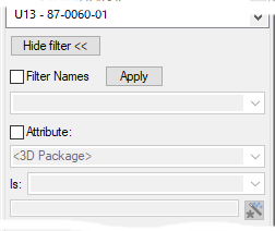
Click on the Use Filter or Change Filter button if you want to further define the search criteria and reduce the number of components to show. If a filter is currently active, then a label will appear saying Filter is active. to the right of the show/hide button. When the button is checked, a set of extra filter controls will appear to use. These are detailed below. When the Hide Filter button is used, these filter controls will disappear.

Check the Filter Names check box to enable the name filter control. Type a filter string that might contain wildcard characters ’*’ and ’?’ into the control underneath the Filter Names checkbox. Use the drop down list to obtain previously used filter strings. Press Apply to apply the filter string to the list of names.
Further filtering of items can be done using an attribute condition.
Check the Attribute check box to enable the attribute condition controls. Use the drop down list underneath the Attribute check box to choose the attribute name you wish to use. Next use the Is dropdown list to select the type of test to apply to the attribute value. Then, if the test requires a condition, select the remaining edit box and type in a string representing the condition to test against.
Sorting
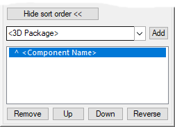
Click on the Show Sort Order or Change Sort Order button define or modify the order that items appear in the component bin.

When the button is checked, a list showing the sort order, and several controls that allow you to modify
it, will appear. The information shown in the sort order list is a either the ^ or the v
character followed by
For example: ^
Click the attribute component box then use the drop down list to choose a new attribute to filter by.
Click the Add button to add this attribute to the sort order list. To modify items in the sort order list, click an line to select it. Once selected, the Up and Down buttons will move the selected line up or down respectively. To remove the selected line, click Remove.
To change to or from an ascending sort order, click the Reverse button.
Adding items to the Component Bin
Items can be added to the Component Bin in numerous ways:
- By checking the ‘Unplaced items to bin’ option when using the Translate to PCB facility.
- By checking the ‘Add Components to Bin’ option when using the Synchronise Designs facility.
- By checking the ‘Add to Comp Bin’ option when Adding a Component or Adding a Connector Pin in Schematics.
- By selecting the Move To Component Bin option in the Autoplace Parameters dialog.
- By explicitly dragging a component, documentation symbol, or connector pin from the design view and dropping it into the Component Bin. To be dropped in to the Component Bin the item must be dragged with the left-hand mouse button held down. If the item is locked or routed, you will be given the option to continue or abort the operation. Multiple items may be selected and dragged in a single operation by using the Ctrl pick or Shift pick techniques.
- By selecting a component, documentation symbol, connector pin, or testpoint in the design view, clicking the right mouse button and selecting Move To Bin from the context menu. This operation may be performed on more than one selected items at the same time.
- Importing a netlist that does not contain any positional information will place the components into the Component Bin.
Placing items from the Component Bin into the Design
The currently selected Component Bin items, i.e. the ones whose names are highlighted in the list and which is shown in the preview window, can be dragged from the bin and dropped in to the active design view by pressing and holding the left mouse button over the Component Bin window and then dragging the items using the mouse to the desired position in the design and releasing.
When dragging multiple components from the bin in this manner they are arranged in a line of columns for you to place together. Whilst moving them you can right click and switch the arrangement between horizontal line of columns and vertical line of rows. The Arranged Horizontally check appears on the context menu, uncheck it to arrange vertically. This option is remembered for next time.
To adjust the maximum width of these rows (or columns in horizontal mode), right click on the component bin and then choose Set Drag Out Row Width from the context menu.

In the dialog, type a number into the dialog that appears to set the maximum row width (or respective column height).
Alternatively, in the active design view, with nothing selected, click the right-hand mouse button to display the context menu, then select the Move from Bin option. The next item from the Component Bin will be moved in the design ready for positioning. When placement of that item is completed by clicking the left-hand mouse button, the next item will automatically be presented ready for positioning, and so on until the Component Bin is empty. This sequence may be interrupted at any time by pressing the Escape key.
The Autoplace option will automatically take items from the Component Bin and place them in the design according to its defined constraints.
Using the Component Bin
With components stored in in the Component Bin you may select the required item by clicking on its name in the list. The selected item will be displayed in the preview window and may be dynamically dragged into the design.
For hierarchical items, such as Components and Connectors in Schematics, you can expand and collapse the associated list of subitems by clicking the item.
Right clicking the mouse anywhere in the Component Bin window will display a context menu. As well as the standard Dockable Window options this provides options to Add to Bin new components via the Insert Component dialog, Delete from Bin the currently selected Component Bin item or Empty Bin of all items.
Items in the Component Bin can be sorted by component name or by group name. The Sort by
�
Schematics Used Items Section
For Schematics designs the component bin is split into two sections. The normal unused section containing spare gates and edge connector pins not currently used in the design, and a section labelled USED ITEMS containing gates, testpoints and connector pins that are on nets in the design. These used items are usually created in the bin by running the Reverse Engineer option, or by using the Synchronise Designs option with the PCB as the master design.
Using Synchronise Designs, the gates of a new component will be added to the relevant USED or UNUSED section of the schematic bin, but if the component is completely unconnected, one gate is always added to the USED section to indicate a new component has been added by the option.
When moving connected items to the bin they will normally be disconnected and become unused items. The exception to this is when the schematic is in SAFE MODE and so the netlist cannot be changed. In this case the item will have its physical connections removed, but the pins will remain on their nets, and the item will be placed into the USED ITEMS section of the bin.
The scope of a gate, testpoint or edge connector in the used section of the bin will be shown if its pins are on local nets within a block. The scope is the name of the block instance, and it indicates that the gate can only be dragged onto a page within this block instance. You will not be able to drag it onto a page where any of its nets are not in scope.
When dragging used items from the schematic bin, it is a good idea to have Connect Guides displayed to show a line to the nearest already placed node on the net for each pin.