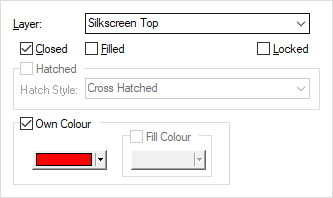
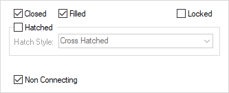
This dialog is displayed when the Properties option is chosen with a Shape item selected.
It shows and allows you to modify properties for the selected Shape item.
Shortcuts
Default Keys: I or Alt+Enter
Default Menu: Edit
Command: Properties
Locating this option
Available from: Edit menu > Properties option
Available from: Context menu > Properties option
Available from: Shortcut key > I
Using the Shape Properties Dialog

Layer (PCB)
You can change the Layer the shape is on by selecting another layer from the drop down list.
The list will also contain Layer Spans if these have been defined for the board and if the shape is capable of using them. For example, for an Area or Board outline spanning inner layers used for flexi-rigid boards.
Drawn on Page (SCM)
In Schematics, you can define which pages the shape is Drawn On. Use This Page Only to define a shape which is only drawn on the current page. Use All Pages In Design to draw the shape on every page within the design (This is useful when defining shapes in a standard page outline). Use All Pages At This Level to draw the shape on all the top level pages within the current block.
Closed
Making an open shape Closed by checking the Closed box causes the start and end points to be joined, with an additional line segment if necessary. Changing a closed shape to open disconnects the start and end points, but no line segments are removed.
Filled
To make a Closed shape Filled, check the Filled box.
A Closed shape will only be filled if it has a solid Line Style pattern.
Locked
To make the shape Locked against changes, check the Locked box.
Hatched
A Closed and Filled shape can be Hatched by checking the Hatch box. You can then select the appropriate Hatch Style from the dropdown list. The hatch lines are drawn in the current Line Style defined for the shape, and the distance between the hatch lines is determined by the width of the line style and the coverage defined in the hatch style.
Own Colour - Documentation Shapes Only
Documentation shapes can be drawn in their own colour, this colour is used irrespective of the colour defined for that item in the Colours Dialog. You can also define a fill colour, so that the outline and fill of the shape are drawn in different colours.
No Spacing Errors Within Footprint - Copper Shapes in Footprints Only
Use this check box to prevent the Component Copper from producing design rule errors against other items within the same Footprint. This is useful if you wish to create internal connectivity between pads which will be connected to different nets externally (for example, a spiral inductor).
Non Connecting - Copper Shapes Only

When checked, the selected copper is marked as Non Connecting. Non Connecting copper can remain isolated and does not have to be connected to the rest of the net although it does still retain the same net name. It cannot be used to form part of the connectivity between other items. Connection optimisation will not add a connection to this copper. This option can be set on all isolated copper produced during a Pour operation. Reports, such as the Net Completion report will not report Non Connected copper as an error.
Additional Information
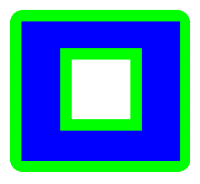
The section at the bottom of the dialog gives some information about the selected shape. The area of the shape enclosed by the centre line (taking cutouts into account) is given in the current design units. You are also given the area taking the width of the style and the roundedness of the corners into account, this will of course be the actual area of the plotted shape. You also get a count of the number of shape segments which make up the perimeter and a count of the number of cutouts.

Shape area including and excluding the style width.
Related Topics
Shape Editing
Edit Shape | Insert Polygon | Filled Shape | Closed Shape | Lock | Hatch