There are two options to enable you to import STEP files. The method chosen will depend on what position you are in your design process and what you are attempting to import. Both processes will use STEP files that have been created or modified in another Mechanical system, for example, Solidworks
Import STEP Board - this enables just the board outline to be imported. See Import STEP Board for more details.
Import STEP Component Positions (this page) - once the design has been placed in Pulsonix, this option can be used to read a STEP file containing Component positional data. It will compare the current positions of the components with positions of the components as described in the STEP file. If there are any changes you will be asked if you to apply the changes.
Shortcuts
Default Keys: None
Default Menu: 3D Design
Command: Import STEP Component Positions
Locating this option
Available from: 3D Design menu > Import STEP Component Positions option
Using the dialog
Use this option once your design has been placed in Pulsonix but positional changes are required once made in the mechanical environment.
By default, all units in STEP files are defined in mm. If your design is set as Imperial, during import, the units will be converted.
-
From the 3D Design menu, select the Import STEP Component Positions option.
-
Select the STEP file required and press Open
-
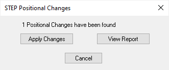
Before the import takes place, a confirmation dialog is displayed. This also reports the number of positional changes that have been found and can be made to your PCB design.

-
From the dialog, use View Report to verify which components have changed.
-
Select Apply Changes to make the Component positional changes.
Outputting STEP files
A STEP model of the PCB can be output using the Output STEP File option.