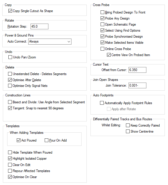
This tab allows you to setup parameters which define how various PCB interaction options behave.
Shortcuts
Default Keys: O
Default Menu: Tools
Command: Options
Locating this option
Available from: Tools menu > Options > Interaction > page
Using the Interaction Options Tab

Copy
Check Copy Single Cutout As Shape to make Copy take a single selected cutout and turn it into a single shape on the clipboard. This can then be used by the Paste command within the Insert Cutout and Insert - Merge operations. Leave unchecked to always copy the whole shape containing the selected cutout.
If you copied a single cutout with the “Copy Single Cutout As Shape” Interactive option set, you can paste this as a cutout by preselecting the target shape or another cutout associated with the target shape. The pasted cutout will be added as a cutout to the selected shape.
Rotate
Rotation Step, defines the angle of rotation for the Rotate One Step command.
Power & Ground Pins
When adding components with predefined signals, or a type of Power or Ground on the part pins, you can choose if they are automatically connected to the appropriate net. You can also choose to always be prompted with the Select Signal for Pin dialog before each pin is connected, or for such pins to Never be automatically connected. If there is a choice (for example more than one power net), then you will be prompted anyway.
Undo
Undo Pan/Zoom, allows you to turn off pan and zoom when performing Undo.
Delete
Unextended Delete - Deletes Segments - This option only applies when using Unextended Delete. Check this box if you want to be able to just delete the selected segments and leave the rest of the shape. This option applies to tracks, copper and documentation shapes. Deleting a segment from a filled shape will open the shape and loose its filling.
Optimise After Delete, when checked, causes Optimise to be run on any nets affected by the delete.
Optimise Only Signal Nets, when checked, causes Optimise to be run only on signal nets (as defined in their net class) when performing interactive operations such as delete and unroute track path. This may significantly enhance performance on designs with large ground nets, whilst still optimising most nets. It may be preferable to enable this option rather than turning off the Optimise After Delete option above.
Construction Lines
Bisect and Divide: Use Angle from Selected Segment, with this mode selected, when using Bisect or Divide, instead of using a horizontal or vertical line, it will use the segment selected regardless of its angle. Without this option selected, you can enter Selected Segment mode by pressing the Ctrl key when choosing the segment.
Tangent: Snap to nearest 90 degrees, with this option selected, when using Tangent mode, the Construction Line will be added at 90 degrees rather than wherever the cursor is in free movement mode.
Templates
These are options related to Templates and Pouring Copper.
Act Poured, when checked, causes new, unpoured templates to behave as though they were copper areas for connection and Optimise purposes. That is, the template can have connections going to it. This means that you get a more realistic connection pattern, without having to pour the template. Pouring templates is often best left until near the end of the design process. Once the template is poured, it can no longer have connections, any connections are transferred to the poured copper.
Pour On Add, when checked, causes newly added templates to pour immediately. This could be useful, if you are adding templates near the end of the design process.
Hide Template When Poured, when checked, causes poured templates (those with some associated copper shapes) to be hidden. They become unhidden when cleared.
Highlight Isolated Copper, when checked, causes any generated isolated copper to be highlighted.
Clear On Edit, when checked, clears the poured template of copper when editing its shape.
Repour Affected Templates, when checked, causes poured copper to be regenerated around items that have been interactively edited. Gaps will be healed and new gaps created according to the current spacing rules each time an editing action is completed.
Optimise On Clear, when checked, the appropriate net will be Optimised after the Clear command.
Cross Probe
Bring probed design to front, when checked, causes the window of the probed design to come to the front. This may be desirable is you are using Cross Probe to perform some interactive operation in the probed design.
Probe Any Design - Uncheck this to only probe the design with a matching name to the one you are currently editing. If there is no matching design, all open designs will be probed.
Open Schematic Page - Check this to cause closed pages to open if an item on that page is probed.
Select Using Find Options - Check this to cause the corresponding probed item to be found using the same settings used in the find bar. Example: Flash It!
Probe Synchronised Design - Check this to find the probed item in the synchronised design.
Make Selected Items visible - When this option is checked, any selected items in the design (selected via cross probe) will attempt to become visible and turn on their layer so they can be seen following the probe. The default is for this to be enabled (to always make visible).
With this option unchecked, layers will not be switched on (or redrawn) which is helpful for very large designs where one might not want layers toggling after a cross probe.
Online Cross Probe - Check this to enable automatic Cross Probe while selecting items. All cross probing then carried out will be in real time dynamically.
Centre View On Probed Item - When enabled, selected items from an online cross probe can be centred on the view in the other design to make it obvious where the selected item is..
Cursor Text
Some interactive operations may display information text next to the cursor. For example, displaying track length limits when editing tracks. Use Offset from Cursor to define how far this text is from the cursor. You can also use the Reposition Cursor Text command whilst cursor text is displayed to change its position relative to the cursor.
Join Open Shapes
Set the Join Tolerance that will be used by the Join Open Shapes function. If the adjacent ends of two open shapes are within this distance they will be joined together.
Auto Footprints
Automatically Apply Footprint Rules - Check this to allow Footprint Rules to automatically select an alternative footprint for a component, if necessary, when performing interactive tasks such as Mirror.
Apply after Rotate - Check this to additionally allow Footprint Rules to automatically select an alternative footprint, if necessary, when interactively rotating a component.
Note that both of the above options are only relevant if you are working with the Use Rules to Auto-Select Footprints option enabled.
Differentially Paired Tracks and Bus Routes
These options provide help with editing paired tracks and bus routes in a PCB design. When adding paired tracks or a bus route with an even number of tracks, the centre line of the “gap” is added on grid and tracks are created either side of this line. This can be a little hard to use and sometimes, due to the tight pattern of the path added, the track lines cannot be added at a consistent distance apart.
Keep Correctly Paired - Check this to stop doubling back and acute corners when adding or editing paired tracks and bus routes, where the tracks end up curved or further apart than the required gap. This mode can be a bit restrictive as it only allows valid track segments. Uncheck it to allow full movement, which was the only mode on earlier versions of the program.
Show Centre line - Check this to show the line between the paired tracks or at the centre of a bus route. This is the line that you are actually editing on the current grid. This helps with seeing that it is on grid and shows the selected dynamic segments. The line is removed as soon as the edit, move or move corner is complete.
Route Selected Nets
Display Strategy Dialog, when checked will invoke the Advanced Autorouter dialog when using Auto Route Selected Nets option. You can then change the number of passes and rules that you want the router to perform on the selected nets. If this is not checked a default set of passes and rules will be used.
Options for Panel Editor
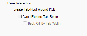
When running this dialog in the Panel Editor, there is an additional option that can be used.

Create Tab-Rout Around PCB Avoids Existing Tab-Routs
This is split into two sections:
Avoid Existing Tab-Routs, this will back off the tab rout so it does not cover an existing tab-rout.
Back Off by Tab Width, this will back off by the tab width set in the Panel Tab-Rout defaults and add mouse bites if they are enabled.
With both options off the tab-rout will rout over the existing tab.
Other Options Tabs
| General Options: | Design Backups | Display | Edit Shape | File Extensions | Find | Folders | General | In-Place Names | Macros | Move | Multi-Screen | Pan & Zoom | Resolve Net Names | Select | Synchronisation | Tooltips | Warnings |
| PCB Options: | Edit Track | Online DRC | Track Length Limits |
| Schematics Options: | Edit Connection | Interaction | Online ERC |
| Footprint Options: | Edit Breakout |
Related Topics
Attribute Names | Advanced Router | Insert Template | Grids | Join Open Shapes | Layers | Rotate One Step | Select Mode | Optimise | Part Editor - Net Names on Pins | Pour Copper