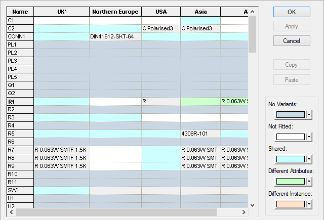
The Component Variant Spreadsheet dialog is available when the design has variants defined. It presents components in a table showing their status in each variant of the design.
If components are selected in the design before entering this dialog, a warning dialog will be presented asking if all components are to be edited, or just the selected components.
Shortcuts
Default Keys: None
Default Menu: Edit
Command: Edit Component Variants
Locating this option
Available from: Edit menu > Component Variants option
Using the dialog
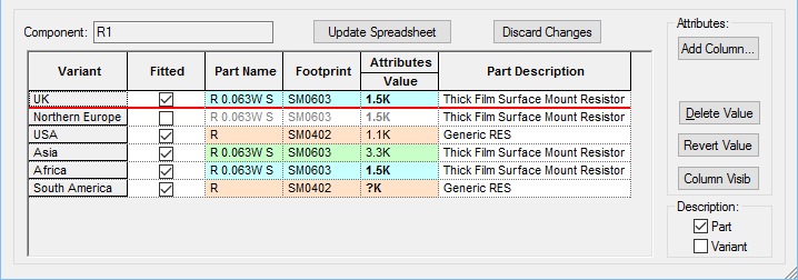
The dialog is split into two parts; the top half is the component variant spreadsheet, with a row for each component and the variants name listed across the top of the spreadsheet. The bottom half allows you to see and edit the variant details for the component currently selected in the top half of the dialog.
Components Spreadsheet Buttons
The buttons down the right hand side of the dialog allow you to Copy and Paste variant information between components and define the colours used for the different variant states
OK - This will Apply any component variant changes to design and exit the dialog.
Apply - If this button is enabled it means there are component variant changes in the spreadsheet that have not yet been committed to the design. Pressing this button will apply these changes to the design, but remain in the dialog for additional editing.
Cancel - This will exit the dialog without changing the design.
Close - The Cancel button becomes Close after using Apply after making changes. Pressing this button will exit the dialog and discard any changes you have been made since the last Apply was performed.
Copy - This will remember all the information shown in the Component Variant grid for the current component. This information can be subsequently copied to another component by selecting the target components row in the spreadsheet and pressing the Paste button.
Paste - This will copy the remembered variant information from the previous Copy action to the current component, or multiple selected components, in the spreadsheet. Part names, fitted state and sharing information will be copied. Only use this feature on components that are to be same part and want to appear the same for all variants in the design. A warning dialog will be shown if any of the components to be changed will have their parts changed. This helps identify if you are pasting to the wrong component. The paste operation can be cancelled from this dialog and the warning can be switched off using the Options Warnings tab.
Resizing the Dialog
This dialog can be resized by dragging any of its edges or corners. The spreadsheet grid at the top of the dialog will be resized by the amount you have resized the dialog by, and the other controls will be stretched or moved to fit around it.
If you hold the Shift key down whilst resizing, the Component Variant grid in the bottom half of the dialog will be resized, and the spreadsheet grid in the top half of the dialog will only be horizontally altered. This is useful if you have a lot of variants to enlarge the lower grid to be able to see them all at the same time.
Component Variants Spreadsheet
The main grid shows a row for each component and a column for each variant in the design.

Cells in the variant columns are colour coded to show the state of each component in that particular variant. The colour indicates whether the component is Not-fitted, is a different Part, uses a different physical appearance (symbol or footprint) or different attribute values. This makes it easy to use the spreadsheet to quickly see which components in the design use variants and which are Fitted or Not-fitted in certain variants.
The first column shows the Component Name. The Part Name is shown in the component variant grid at the bottom of the dialog
Variants used in the design are listed across the top of this pane. The variant columns only show a Part name for a component if it is different to the main part. The part name cannot be edited in this grid, but can be changed by editing its value in the component variant grid at the bottom of the dialog and then updating the spreadsheet with the changed component.
The Name and Variant columns can be sorted alphabetically by clicking on their column headers. Clicking on any cell apart from the column headers will make the component the row represents the current component and will change the lower grid to show its variant details.
The current component is indicated in the spreadsheet using a bold text style in the component Name column. When clicking on a different row to change the current component, and if the lower grid has variant changes pending, you will be asked if you want to update the spreadsheet with these changes prior to switching the current component.
You can select multiple components in the spreadsheet by dragging the left mouse button down in the Name column. The only use for this is to use the Paste option to copy the same variant information from another component to multiple components.
Cell Colours
The next set of buttons show the colours that will be used for each variant ‘state’ in the dialog. Click on a colour block to change its colour. The colours are retained in the system registry, so that your choice of colours is preserved for future use.
No Variants - This colour is used for all cells of a component that does not vary for any variant.
Not Fitted - This colour is used for cells where a component is not fitted in the variant the cell represents.
Shared - This colour is used for cells where a component is fitted in the variant the cell represents and it shares the same part name, attributes and physical component instance as the ‘normal’ component.
Different Attributes - This colour is used for cells where a component is fitted in the variant the cell represents, but it has a different set of attributes to the ‘normal’ component.
Different Instance - This colour is used for cells where a component is fitted in the variant the cell represents, but uses a different physical component instance to the ‘normal’ component.
Instances are discussed on the Advanced View in Variants page.
Component Variant Details
The bottom portion of the dialog is occupied by a grid showing the variant details for the currently selected component in the spreadsheet.

This grid is similar to the Component Variant Properties dialog, but with the added ability to add and modify Attributes and Values.
It contains a row for each variant in the design and columns allowing you to change the components fitted state, part name, and whether it has a footprint or whether it has different Attribute Names or Values. Cells in these columns are coloured depending on their ‘state’ using the same system as the Component spreadsheet above. The name of the variant currently active in the design is shown in bold text in the appropriate row. the currently selected row is underlined in red.
The table can be enlarged to show more variants, see Resizing the Dialog section above for details.
Changing Variant Details
Variant - This column lists all the variants in the design. The name of the variant currently active in the design is shown in bold text.
Fitted - This column enables you to change the Fitted and Not-fitted status of the selected component, (components are fitted in all variants by default). The check boxes is selected to indicated the component is Fitted or unchecked to indicate it is Not-fitted. By default, a component is considered fitted in all variants unless explicitly set as Not-fitted by un-checking the Fitted check box in this dialog.
You cannot select the Not-fitted status for all variants for the selected component, at least one instance must be fitted.
Part Name - This column shows the part used for the current component in that variant. You can use this column to change the part used for this component. By double-clicking on the Part name in the cell the Change Part dialog will be presented for you to choose the required part.
Footprint - This column displays the footprint for the current component in that variant. You can use this column to change the footprint used for this component. By double-clicking on the Footprint name in the cell the Change Part dialog will be presented for you to choose the required footprint. You can change the footprint without having to change the Part, the dialog allows this.
Attributes - The attribute columns and values can also be modified within each variant.
Shared Identifiers in Variants
An advanced form of variants is to use a different component instance in some variants, this called a Shared Identifier. If at any point, you wish to create or edit a Shared Identifier then right click and select Advanced Viewfrom the context menu.
Shared Identifiers can be used for a number of reasons: you may wish to have a different component position (in PCB) for the different variants. This might be because the footprint is larger and requires more space or because it has a wider (or smaller) pad pitch or even drill hole size. Another possibility is that you wish to identify an instance in a variant. You can only do this by having a different instance. This in turn means the component has it’s own instance identifier which can be extracted in the Report Maker for example or viewed in the Component Properties,
Dialog buttons
Update Spreadsheet
This button becomes enabled when you have changed one of the cells in this grid. Press the button to update the main spreadsheet with the changes for this component. The changes will not be committed to the design until the Apply or OK buttons are pressed to apply the changes to all the components in the spreadsheet.
Discard Changes
This button also becomes enabled when you have changed one of the cells in this grid. Press the button to discard any changes you have done to the current component and restore the values in the grid from the component in the main spreadsheet.
Attributes
You can add a column showing a particular attribute name and all the values for that attribute for each variant. This enables you, for example, to change the value of a generic resistor for each variant. To change the value, left click in the cell and type the required text.
The buttons to the right-hand side of the grid provide you with tools to Add and Edit the Attributes and their values. Some buttons may only be enabled if appropriate cells are selected in the grid.
Add Column - This will add another Attribute Name column to the Attributes section of the grid. This allows you to add new attribute names and values to that component. Choose the Attribute name from the drop down list presented. This name then appears in the attributes list.
Delete Value - Depending on what is selected in one of the attribute value cells, this button will either be Delete or Reset.
Delete will remove the attribute from the selected cell. Reset will reset the selected cell to its inherited value.
Revert - Use this button if you have accidentally modified the wrong cell but do not want to cancel the whole dialog. Pressing Revert will return just the selected cell to its original value from the design. This button will only be enabled if the selected cell has been modified.
Description - Part and Variant
There are two optional check boxes to the bottom right of the dialog that add columns to show the description of the Part and Variant used in the row.
The Part Description is taken off the Part. The Variant Description is taken from the description assigned for the variant in the Variant Manager.
Fitting and Unfitting Multiple Components
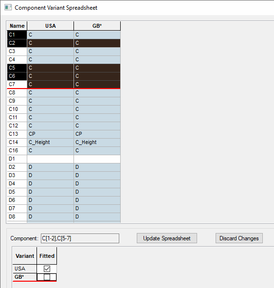
You can Fit (or Unfit) multiple components with simplified variants at once using this spreadsheet.
You can do this by using the Ctrl and Shift keys to select the required components in the spreadsheet list.
They must initially have the same fitted status before you Fit or Unfit them.
Once selected, the Variant Details pane changes to a simplified version that only allows the fitted status to be changed.

Once your changes have been made, either select Update Spreadsheet or Discard Changes to make the changes permanent or to discard them.
Using the Database Connection (PDC) with Part Variants
If you have the Pulsonix Database Connection cost option and it is enabled, the Component Variant Details pane will display an additional Database column next to the Part Name. This displays the component’s database key field information for each variant and is useful for seeing if database part variants are being used even if the Pulsonix Library part is the same across variants.
When changing a Part using the Database field which has been chosen using the Database Bar, double-click on the cell in the variant you wish to change. The Database Bar, will be displayed. From this, make the part selection required.
Note that if the Part Name is changed for a variant, unless it is chosen using the Database Bar, any existing database information will be lost and it will revert to being a ‘local’ component for that variant. For a ‘local’ component, the Database column will be blank.
Related Topics
Attribute Names | Component Variant Properties | Pulsonix Database Connection | Variants | Show Hide Attribute Name Columns | Advanced View in Variants