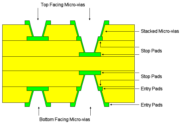
A micro-via is a laser drilled hole which connects two layers by drilling through the Entry pad on one layer of the two layers and connecting to a Stop (or capture) pad on the other layer.
Locating these options
Available from: Setup menu > Technology > Styles - Pads tab
Available from: Setup menu > Technology > Layers - Layer Spans tab
Available from: Setup menu > Technology > Rules DFM/DFT - Net Styles tab
Defining Micro-Vias
Micro-vias are defined between two layers (the layer span). What defines a micro-via span is that the two layers face the same way as defined in the Layers dialog and the stop pad is not drilled.
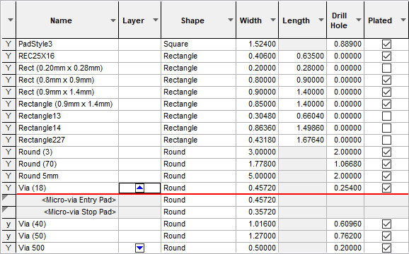
The Entry pad and Stop pad sizes for micro-vias are set up as special pad style exceptions to ensure the correct via size and type is defined on the two layers that define the span of the via. These provide a simple method of defining specific Entry and Stop pad sizes, they are not mandatory for Micro-vias though.
The micro-via pad definition (using Entry and Stop pads) is used for creating tapered Micro-vias, where the Entry and Stop pads are different diameters to match the taper effect caused by the laser drilling.

You will be able to define composite layer spans that represent a vertical stack of Micro-vias of different sizes that are drilled separately. When this span is used it causes multiple vias to be added rather than a single via. All vias in the stack can then be selected and moved as one item. This will create a stacked tapered Micro-via:

It is possible to stack micro-vias, each step of the stack being drilled separately. To ensure both vias in the stack have coincident coordinates (so they align when positioned) you would need to define a Composite layer span. Without Stop pads, the laser will simply cut to a depth or until it reaches a Stop pad. Multiple tapered via spans are also possible using Composite Layer Spans using different Via Pad Styles.
In the Net Styles dialog, define the style to be used for each stage of the span for the appropriate Net or Net Class. When editing a track, Change Layer may then create a stack of vias to change layer, rather than a single via. This process is show in more detail below.

Creating Entry and Stop Pads for Micro-Vias
The procedure below details how to create Entry and Stop pads for micro-vias:
-
In the Technology, edit the Pad Style and use the By Layer option.
-
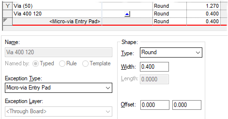
For Exception Type: select Micro-via Entry Pad from the drop down list.
-
The Exception Layer: box will now be greyed out as not selectable.
-
Type a value for Width: if it needs to be different to the default stack value, moving off this grid or pressing Apply will save the exception.

-
Normally, you would also do the same for the Stop Pad so the laser knows where to start and where to stop drilling, although this is not mandatory for some processes. The Stop pad is displayed as a solid pad even though the default pad stack is defined with a drill hole, and the Entry pad is displayed with a drill hole shown (depending on Layer Class).
-
The Pad Style entry for that pad would then look like this (shown for our example Via 400 120):

Special Note about Drilling Micro-vias
Micro-vias are drilled (using a laser or plasma drilling machine) using the standard Excellon NC Drill output. Special customised reports can be generated using the Report Maker option. All pad styles on any layers and the drill position can be output if required..
Related Topics
Technology - Layers | Technology - Layer Class | Technology - Layer Spans | Net Styles | Change Layer | Insert Via | Entry and Stop Pad Sizes | Report Maker