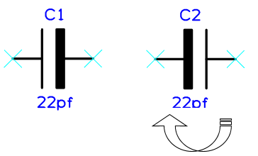
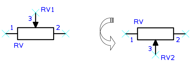
Use the Mirror Vertically or Mirror Vertically commands to reverse the image of selected items, either in the X direction, or in the Y direction depending on your requirement. Using Mirror Vertically in a PCB design, it will flip components to the other side of the board.
Shortcuts
Default Keys: M
Command: Mirror Horizontally
Default Keys: None
Command: Mirror Vertically
How to Mirror an item:
- Select an item in the design and use the Mirror Vertically or Mirror Vertically option from the shortcut menu.
- Whilst dragging item(s) to place them, use the Mirror Vertically option from the shortcut menu to mirror them on the fly.
Mirror Options
Below is an example of a Schematic Symbol Mirrored Horizontally:

Below is an example of a Schematic Symbol Mirrored Vertically:

Mirroring Groups of Selected Items
If many items are selected, then they are mirrored as a group about the item that was picked last. This item is shown on the status bar at the bottom of the screen. If there is no picked item, when using frame select for example, the items will be mirrored about a gridded point at the groups centre.
Mirror in Latched mode
Mirror can be run in a Latched Mode. This means the mirror operation is invoked when there is nothing selected in the design. The mirror tool will be “latched down” allowing you to mirror items as you pick them. This will continue until the Esc key is pressed or another operation is started.
Defining The Mirror Origin
You may wish to change the point in an item that it is mirrored about. For example, if you have defined the origin of a component at its centre, but wish to mirror it about the first pad position.
If mirroring a pre-selected item, you can change the selection origin by using Place Selection Origin from the shortcut menu. Place the origin over the item or point you want to mirror about and then use the Mirror function.
Alternatively, when the Mirror option is latched down, you can redefine the point to mirror about as follows:
Right click and use the Use Selection Origin option from the shortcut menu. A origin symbol will be displayed on the cursor for you to place. Whilst placing it, right click again to enable the Snap To Item option if you want the origin to snap to the nearest point on the design item it is dropped over. Once the origin has been placed you can right click and use Place Selection Origin to reposition it.
With a selection origin defined, the operation will use it to mirror about.
Mirroring in PCB Designs
The mirror command, when applied to Components, flips the component to the other side of the board and mirrors it’s image. The PCB design is viewed from the top, so any components that are on the bottom side need to be mirrored to view correctly.
If the component has surface mount pads then after mirror they are on the other side of the board, so any tracks attached are adjusted. The track segment attached to the pad is swapped to the same side as the pad and a via is inserted at the end of the segment to reach the rest of the track’s segments.
Shapes, text and attributes on the component change layer to the layer of the same layer class on the other side of the board. If there is no swap layer, these items will stay on their original layer.
If Footprint Rules have been defined and are set to be applied automatically then mirroring a component may result in it switching to an alternative footprint.
You can also perform Change Layer on an Embedded Component, this will allow you to change the layer of the component to any other layer with suitable non-electrical layers. Normal components can also be placed on inner layers using Change Layer when using Flexi-Rigid Boards and Boards with Cavities.
Mirroring in Schematic Designs
Mirroring Bus Terminals in Schematic Designs
The only exception to the way mirror works is for schematic bus terminals. If only bus terminals are selected and they are on orthogonal bus segments, they will be mirrored along the bus segment by moving only the bus end of the terminal. The connection end will stay where it was. The only exception to this is where the mirrored bus end of the terminal ends up off its segment, in which case it will be shifted back to the segment end.
Mirroring in the Panel Editor
You can use both the Mirror options within the Panel Editor for a selected PCB instance.
In order to mirror the instance, there must be matching ‘opposite’ sets of Layers defined in your Technology in order for the mirror to be performed.
Related Topics
Technology | Board Cavities | Flexi-Rigid Boards | Latched Mode | Layers