IDF is a neutral data format which can be exported from 3D mechanical design systems. Pulsonix can import Board, Area, Component Placement and Mounting Hole data from this format. IDF data is generally output as a board file and a library file. Pulsonix only imports the board file.
IDF files are equivalent to DXF files but are used mainly by 3D mechanical systems such as SDRC Ideas, Solidworks and ProEngineer, (other systems may also use this file format, these are only examples).
Shortcuts
Default Keys: None
Default Menu: File
Command: Import Design Data
Locating this option
Available from: File menu > Import Design Data > choose IDF Files *.idb
Importing IDF
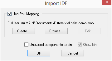
You must have a PCB design open. Select Import Design Data from the File menu. You can then browse for the IDF file that you want to import. You will then be presented with the following dialog.

Most component data will have positional information, but some may be unplaced. Check Unplaced components to bin if you want imported components which are unplaced to be placed in the Component Bin as opposed to being placed at a random position on the design.
Check Show Bin if you want the component bin to be displayed after importing the IDF data.
Part Mapping
In general the names used for parts should be the same. But if there are parts that have slightly different naming system, or the parts that are not in either the standard Pulsonix libraries or your own, then you can map the part names to names that exist in your libraries.
Similarly you can map the footprints that you want to be used in the design.
Check Use Part Mapping to allow the part mapping option.
Create will create a default mapping from all the parts and footprints used in the IDF file. You will be prompted for the name of the file that you want to save the mapping to, The Part Mapping Editor will then be invoked for you to change the mapping.
Browse allows you to browse for an existing part mapping file. This will load the mappings into the Part Mapping Editor and will top up any parts that do not exist in the mapping. Any changes to the mapping will be saved to this mapping file.
Edit allows you to re-edit an existing part mapping file.
Shapes in “Other Outline” sections will be imported as copper shapes unless their identifier starts with “BOARD” in which case they will be imported as additional board outlines.