It is possible to probe a bus as long as it is a closed bus and all the signals on the bus are digital. In this case a plot representing all the signals on the bus will be created. Usually this will be a numeric display of the digital bus data, but it is also possible to display the data as an analog waveform.
The Define Bus Probe dialog is used in two situations:
- To edit Fixed Bus Probe components in a schematic design. The Bus Probe is a single pin component placed with its symbol origin over a bus outline in a schematic design. These components have their Spice Type set to use the Probe - Bus built-in function.
- When using the Random Probe tool to probe busses in a schematic design.
Use the dialog to define the required plot for the selected Bus Probe.
Shortcuts
Default Keys: F7
Default Menu: Simulation
Command: Edit Spice Value/Model
How To Define Bus Probe Values
Select the Bus Plot Probes that you wish to change and press F7 or use the Edit Spice Value/Model option from the Simulation menu, or from the shortcut menu.
Or,
Use Random Probe from the Simulation menu and select Probe Bus from the shortcut menu. Pick the closed bus to plot.
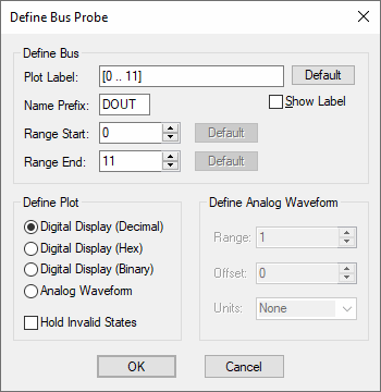
The following dialog will be displayed:

Define Bus
Plot Label - This is how the curve will be labelled in the plot
Name Prefix, Range Start, Range End - Defines which nets in the bus are used to created the displayed data. The default is to use all nets defined in the bus, indicated by range value -1.
Plot Type
Decimal/Hexadecimal/Binary - Each of these specifies a numeric display (see below) showing the bus values in the number base selected.
Analog Waveform - Specifies that the bus data should be plotted as an analog waveform.
Hold Invalid States - If checked, invalid digital states found in the data will be replaced with the most recent valid state. If not checked, invalid states will be shown as an X in numeric displays. This option is automatically selected for analog waveform mode.
Define Analog Waveform
Only enabled if Analog Waveform is specified in the Plot Type box. Specifies the scaling values and units for analog waveforms:
Range - Peak - peak value used for display.
Offset - Offset for analog display. A value of zero will result in an analog display centred about the x-axis.
Units - Select an appropriate unit from the drop down box.
Editing Multiple Probes
If any of the fields are set to