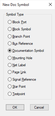
Schematic Documentation Symbols are used for several purposes. It is therefore necessary to specify the purpose of each symbol when it is created. In this way, the program can ensure that the symbol satisfies the requirements of its purpose (for example that it contains exactly one pin) and that you are only presented with symbols of the correct type when adding them.
Locating this option
Available from: File menu > New > Designs tab > Schematic Doc Symbols option
Schematic Doc Symbol Types

There are a number of documentation symbol types:
- Block Port is used within a block to connect with the enclosing level. A block port symbol must have a single pin, and can contain any figures you wish. To add a block port, use the insert block port command. Whilst adding a connection, use End Connection On from the context menu.
- Block Symbol is used to represent a block instance. When you create a block, you can nominate a block symbol to represent that block. You can also choose the symbol when inserting a block. A block symbol must have a pin for each pin in the block it is to represent.
- Branch Point is a symbol used to represent a logical point in a net used to split a track to follow different paths. It is particularly useful when used to add a branch using Insert Branch Point to a Signal Path, or Differential Pair allowing you to use length match rules to match the length of multiple branches.
- Bus Reference is a symbol used to display the nets range on a bus. The symbol must contain a single pin. Whilst adding a bus, use End Connection On from the context menu.
- Documentation Symbol, this can be used in many ways. For example, it could contain a logo. You can add a documentation symbol to a design by using the Insert Documentation Symbol command.
- Mounting Hole is a single pin symbol used to represent a Mounting Hole in the corresponding PCB design.
- Net Label is a single pin symbol used to represent a Net Label in the design. This will be placed on a connection to identify and highlight the Net Name.
- Page Link is a symbol to represent a link to another page. When this symbol is used, it can be associated with another page in the schematic. You can then ‘jump’ to the specified page using the Jump to Page command, when the symbol is selected. Whilst adding a connection, use End Connection On from the context menu.
- Signal Reference is a symbol used to represent a break or link on the net. The symbol must contain a single pin. It would typically be used for a ground or power symbol. Whilst adding a connection, use End Connection On from the context menu.
- Star Point is a symbol used to join two or more related (but different) nets together at a single point in the design at the same time leaving them separate in the netlist. This can have any number of terminals but the nets connecting to them remain independent regardless of whether a single terminal or multiple terminals have been defined. Use insert Star Point to add this item to the design.
- Testpoint which is a symbol used to represent a testpoint. The symbol must contain a single pin. Testpoints can be added using the Insert Testpoint command. Whilst adding a connection, use End Connection On from the context menu.
Related Topics
SCM Documentation Symbol Libraries | Using SCM Libraries | End Connection On
Insert Doc Symbol | Insert Block Port | Insert Block Instance | insert Star Point | Properties - Block | Properties - Block Ports | Jump to Page | Insert Testpoint | Insert Branch Point