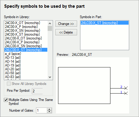
This page is used to select the Schematic symbols to be used for the ‘Gates’ of the part.
How to use this dialog

Symbols in Library
The left-hand list shows the symbols found in the currently available symbol libraries which have the correct number of pins. The pin count is specified in the Pins Per Symbol control below the symbols list. There are two ways of using this as follows:
- If you know how many pins your required symbol has, uncheck the Show All Library Symbols box and enter the pin count in the Pins Per Symbol field. The Symbols in Library list will be updated to show only symbols with the entered pin count.
- If you do not know how many pins your required symbol has, but know the symbol name, check the Show All Library Symbols box. The Symbols in Library list will be updated to show all available symbols. When you select a symbol in this list, the pin count in the Pins Per Symbol field will change to show the pin count on the selected symbol.
If the part is homogeneous (a multi gate part where each gate uses the same symbol) check the Multiple Gates Using The Same Symbol box. The Number Of Gates field will be enabled for you to enter the gate count for the part.
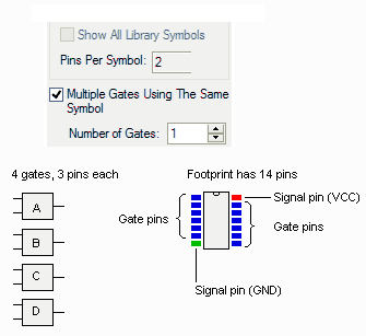
The diagram below shows how the pin counts might be specified for a new part. This part uses a 14-pin footprint, and four 2-input gates each with three pins. The two remaining pins (those not used by the 12 gate pins) are signal pins, and are used to specify the power and ground pins of the part. These signal pins then do not appear on the Schematic drawing, but are automatically connected up when the component is added to the PCB design (if the specified nets exist in the PCB).

Symbols in Part
The right-hand list shows the symbols to included in this part. Select a symbol from the Symbols in Library list and press Add (or double-click on the symbol name) to add this symbol to the part. If Multiple Gates Using The Same Symbol is checked, the specified number of gates will be added and the Add button modified to be Change. Pressing Change will replace all gates in the part with multiple copies of the the symbol selected in the Symbols in Library list.
To remove a gate from the part, select the symbol in the right-hand list and press “Delete”, or double-click on the symbol. Once again, if Multiple Gates Using The Same Symbol is checked, removing one gate from the part will remove all gates.
Preview
This shows a picture of the symbol that was selected in either symbol list last. The name of the symbol is displayed above the picture. Use this to confirm that the selected symbol is the correct one.
If you attempt to move to the next page of the Wizard when building a normal or Schematic only part without first adding a gate symbol, you will be prompted to confirm that you wish to use the symbol currently selected on the dialog.
Vault
If the Vault is in use, the Vault section,
displayed below the right-hand list of symbols,
will show the Vault Item ID and Revision for the
symbol that was selected last in either symbol list.
By default, Revision shows the
A symbol that is not from the vault, will be shown as such in the ID field.

Part Wizard Pages
Start | Type of Part | Part Details | PCB Footprints | Power and Ground Pins | Gate Pins Details | Attributes | Finish