Back Drilling is the process of removing stubs from (mainly) plated through hole (PTH) vias, and can also be performed on component pads and mounting holes. This practice is normally associated with high speed designs. This is achieved by drilling away the via stub using a drill slightly larger than the via. Unnecessary via stubs can lead to signal reflections, capacitance, inductance and impedance discontinuities (these losses can be a major issue in high speed designs).
Some of the Back Drilling advantages are shown below:
- Reduced deterministic jitter
- Lower bit error rate (BER)
- Less signal attenuation with improved impedance matching
- Increased channel bandwidth
- Increased data rates
- Reduced EMI/EMC radiation from the stub end
- Reduced excitation of resonance modes
- Reduced via to via crosstalk
The diagrams below illustrate the board profile before and after Back Drilling. Generally, a stub length between 7 thou and 10 thou remains after Back Drilling.
Before Back Drilling 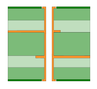 | After Back Drilling 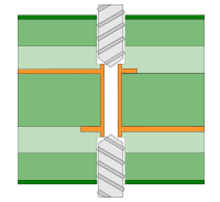 |
The Process of Back Drilling
In order to utilise Back Drilling, the summary below informs you of the process:
- Identify a requirement for it, then:
- Add Spans to accommodate Back Drilling
- Create Back Drilling rules
- Add Vias, Component Pads and Mounting Holes that require Back Drilling
- Export the Back Drilled Vias to the Excellon NC Drilling format using the CAM Plot option.
Adding Back Drill Spans
A Back Drill span is a span of layers over which Back Drilling will be performed. These spans will need to be created in Technology - Back Drill Spans. You can add spans manually by adding new entries into the grid, or auto generate spans by clicking the Auto Gen button. When Back Drill spans are added into the design, they will be assigned to items based on the current layers used by the item, and the defined back drill rules.
Adding Back Drill Rules
By default no items will be Back Drilled. To specify which items should be Back Drilled, rules will need to be created in [Technology
- Back Drill Rules](idh_technology_back_drill_rules.md). These rules define which nets should Back Drill vias, matching the nets based on either net name, net class or net type. You can also specify whether component pads and mounting holes should be Back Drilled. This dialog also allows for defining the size of the oversized drill, and the remaining stub length after Back Drilling.
Adding Back Drilled Items
To add a Back Drilled via relevant Back Drill rules and Back Drill spans must be defined. Once they have been, you can check which Back Drill spans are used for a specific item in Back Drill Properties. If the spans are not correct, you can use the Update Back Drills option on the Utilities menu to correct them.
A Back Drilled via will be shown in one of three possible ways:
Top Back Drill 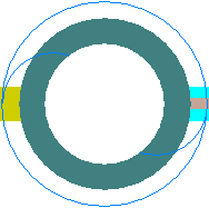 | Bottom Back Drill 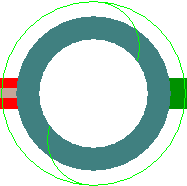 | Top and Bottom Back Drill 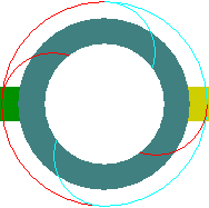 |
The colour of the Back Drill symbol depends on the colour of the Back Drill span, defined in Back Drill Colours. The shape itself is rotated to differentiate between a top and bottom Back Drill span. If the via has both a top and a bottom Back Drill span, then both the top and bottom Back Drill symbols will be drawn, with half of the outer circle the same colour as the top Back Drill span, and the other half being the same colour as the bottom Back Drill span.
Component Pads
In order to utilise Back Drilling for component pads, the pin depth needs to be defined. This depth will be used to calculate the appropriate Back Drill span for the pad. You cannot Back Drill component pads without a pin depth.
To do this, add the
If you need to define the pin depth for all pads on a component, you can instead add the
Note: The Pin Depth attribute overrides the Part Pin Depth attribute. This means that if the Part Pin Depth is defined for the component and the Pin Depth is defined for one pad, the Pin Depth value will be used for that pad, and the Part Pin Depths value will be used for all other pads.
Checking Back Drilled Items
There is a specific check built into the Design Rule Checks dialog that can be used to check Back Drilled Items.
Plotting Back Drilled Items using the CAM Plot option
The CAM Plot option will be used to generate an NC Drill Excellon file that will contain a list of vias that have been specifically defined for Back Drilling.
Units
The Units button allows you to locally switch between Metric and Imperial units whilst in this dialog. Once the dialog is closed, the units revert back to the original design units. If switching to different units to the design units, the value typed will be converted when you next enter this page.
Related Topics
Technology Overview | Technology - Back Drill Rules | Technology - Back Drill Span | CAM Plot - Drill Outputs | Design Rule Checks