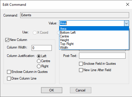
Use these commands within a “List Of …” command to report the extents of an item in the list. If the command is used at the top level of the script, i.e. not in a list, the design extents will be reported, the extents of all items in the design (not just the board outline).
The actual value reported for the extents depends on the Value field chosen in the extents dialog as follows:

Choose from the list of values (shown above) that can be extracted from the items extents. The chosen value will be reported in your current design units or current report units (if the Coordinate Units command has been used previously in the command script).
For New Column and Field Information - click here for dialog details.
Board Extents
This command is used to report the extents of the board outline. Where more than one board outline exists in the design, the first outline drawn will be used. Where a circular board has been used, the extents will be reported based on an orthogonal ‘box’ around the shape. Note, if line width is not relevant to your calculations and you want the board extents to be limited to the centreline of the segments defining its outline, use the Board Centreline Extents command instead, see below for details.
The Board Area value also takes into consideration any board outline cutouts (the total area of any cutouts are taken out of the Board Area value reported).
Example use of Board Extents
Board Extents Bottom Left X Coord
Board Extents Bottom Left Y Coord
The report output looks like this:
25000.0 1500.0
Further example use of Board Extents
Board Extents Bottom Left
The report output looks like this:
(25000.0,1500.0)
Where the command does not show the X or Y Coord wording, the extents X and Y are output.
Board Centreline Extents
This command is similar to the Board Extents command explained above. Use this if line width is not relevant to your calculations and you want the board extents to be limited to the centreline of the segments defining its outline.
Top Placement Extents and Bottom Placement Extents
Use the Top Placement Extents and Bottom Placement Extents commands within a List Of Components command to report the placement areas of Components on the top or bottom side of the board. If body areas are defined in the footprint for a component on the appropriate side, the extents will be the box surrounding all of these areas. If no body areas exist on the appropriate side, the box surrounding all the outlines on that side will be used, and if no outlines exist the box surrounding the pads on that side will be used.
Component areas defined as being
Example use of Top Placement Extents
List Of Components
	Component Name
	Top Placement Extents Bottom Left
	Top Placement Extents Top Right
	End Of Line
The report output looks like this:
U1 (150.9,-399.1) (599.1,-0.9)
U2 (150.9,-899.1) (599.1,-500.9)
Top Placement And Pads Extents and Bottom Placement And Pads Extents
Use the Top Placement And Pads Extents and Bottom Placement And Pads Extents commands within a List Of Components command to report the placement areas of Components on the top or bottom side of the board. If component body areas are defined in the footprint for a component on the appropriate side, the extents will be the box surrounding all of these areas and all pads on that side. If no body areas exist on the appropriate side, the box surrounding all the outlines and pads on that side will be used.
Component areas defined as being
Example use of Top Placement And Pads Extents
List Of Components
	Component Name
	Top Placement And Pads Extents Centre X Coord
	Top Placement And Pads Extents Centre Y Coord
	End Of Line
The report output looks like this:
U1, 150.9, -399.1
U2  150.9, -899.1
Using the dialog
This command uses a common dialog to set up possible parameters. See the Value Detail page for more information.