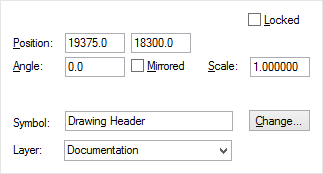
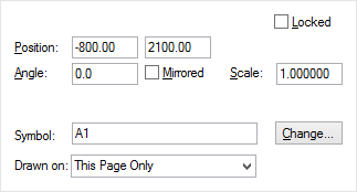
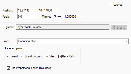
This dialog is displayed when the Properties option is chosen with a doc symbol selected, it shows and allows you to modify its properties.
Shortcuts
Default Keys: I or Alt+Enter
Default Menu: Edit
Command: Properties
Locating this option
Available from: Edit menu > Properties option
Available from: Context menu > Properties option
Available from: Shortcut key > I
Using Documentation Symbols
In Schematic designs, Documentation Symbols are used for documenting your design, such as drawing borders, drafting labels (WEEE, Static, Info etc.). Other Doc Symbols, such as Net Labels, power and ground symbols, Bus References etc. are found under Properties | Signal References.
In PCB designs they have a slightly different use and are used less. They can be used for testpoints, drawing borders, PCB documentation (such as static and WEEE references) and can be used for company logos.
Use Insert PCB Documentation Symbol and Insert Schematic Documentation Symbol to see how to add Documentation Symbols.
Using the Documentation Symbol Properties Dialog

Symbol is the name of the documentation symbol. Use Change Documentation Symbol if you want to change symbol to another one from either the same library or another documentation symbol library.
Layer is the layer that all documentation shapes and text within the symbol will be drawn on.
The coordinates of the symbol can be changed using the Position edit controls.
Angle shows the rotation of the symbol and can be used to change it.
Check or uncheck Mirrored to swap the symbol to the other side of the board.
You can Scale a symbol. A scale of 1.0 represents the symbol at the size it was designed at. All points are scaled relative to the symbol origin. Styles are not scaled, so all text remains at the same height and lines remain the same width.
Check or uncheck Locked to lock or unlock the symbol against moving.

Symbol is the name of the documentation symbol. Use Change Documentation Symbol if you want to change symbol to another one from either the same library or another documentation symbol library.
The coordinates of the symbol can be changed using the Position edit controls.
Angle shows the rotation of the symbol and can be used to change it.
Check or uncheck Mirrored to mirror the symbol about the y-axis.
Check or uncheck Locked to lock or unlock the symbol against moving.
Drawn On specifies on which schematic pages this symbol will drawn. Use This Page Only to specify it is only drawn on the current page. Use All Pages In Design to draw the symbol on every page within the design (This is useful when defining logos in a standard page outline). Use All Pages At This Level to draw the symbol on all the top level pages within the current block. The last two options are not available if the documentation symbol has terminals. This is because you cannot have a connection on multiple pages.

Include Spans specifies which Layer Spans are included in a layer stack preview.
If you wish to have more complexity, then you should use the Report Maker option to create a more specific report that is then added to your design using the Insert User Reports option.
Select the Use Proportional Layer Thicknesscheck box if you wish to represent the preview using a proportional representation of the actual layer thicknesses if defined in the Technology - Layers dialog along with thicknesses defined in the Technology - Materials dialog.
When this check box is unchecked, the layer stack preview will use a fixed size for non-electrical, electrical and construction layers.
Related Topics
Insert PCB Documentation Symbol | Insert Schematic Documentation Symbol | Change Documentation Symbol