Use this option to split a net in your PCB or Schematic design into two separate nets and optionally, to remove one of these split nets from the design.
Note: This option is provided because the Delete function in PCB does not split nets, and in schematics does not always split named nets.
Shortcuts
Default Keys: None
Default Menu: None
Command: Split Net
Locating this option
Available from: Context menu > Split Net option
How To Split A Net
There are three ways to split a net into two using the Split Net option. Two involve selecting an item and then right clicking the mouse to use the shortcut menu. Move the cursor over the Net option and select the Split Net option from the sub-menu. The other method is in schematics where you will automatically enter Split Net when dropping a two pin component onto an existing connection.
-
Select a Connection or Track
The item must be the only physical link between two halves of a net. The connection or track will be deleted and the two halves are split into two separate nets.
-
Select a Pad, Via, Junction, Copper Shape or Template
The item must be on a sub-part of the net that is physically separated from the rest of the net. This sub net will be split into a separate net from the main net.
-
In schematics, drop a two pin component directly onto an existing connection
The connection will be split by inserting the component into it and the two halves are moved into two separate nets.
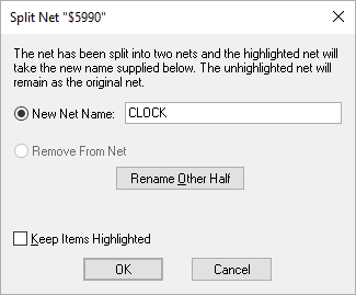
The following dialog is now presented:

The operation will produce 2 nets, one retaining the existing net name, the other either uses the new net name which you specify in the dialog, or is removed from the net altogether (in the case of a track or connection, that means deleting from the design because it cannot exist without a net).
The part of the net which will be split away (renamed or removed) is displayed in the design using the Highlight Colour.
Use the Rename Other Half button to swap the two nets. The two nets alternate between being highlighted. Use this to show where the two nets are, and to choose which net remains as the old net name.
Use Remove From Net (if available) to remove the split net instead of renaming it. All connections and tracks in the split net will be removed and all remaining items in the split net will be removed from being on a net. This is only available when entering the Split Net option from the shortcut menu.
If editing a PCB design, use the Include Connections in sub nets check box to determine how sub nets are derived. If connections are not included, then the sub net is defined as all items which are selected or connected to selected items by tracks only. With connections included, connections can also connect items to the sub net. This can in some cases have no effect, whilst in others cause a profoundly different result.
Use Keep Items Highlighted when a net is split, for example, if a resistor component is dropped on to a net. Selecting this will mean no net highlight will take place. The net highlight is used to indicate the renamed portion of the net. This mode is off by default and can be selected to on for use in the option if and when required.
When you are satisfied press the OK button to keep the change, or use the Cancel button to put the net back together. If OK is pressed and the new net name provided already exists in the design, an error message is shown and you are returned to the dialog.
In schematic designs the main difference to PCB is that if pads would become isolated after the split (i.e they are the only thing left on the net) then you will be warned that these pads will be removed from the net when OK is pressed.
Note: you cannot split a net if all the items on the net would still be connected together. The dialog will indicate such a case, and the OK button is only enabled to allow you to remove the connection or track that was selected.