Measure is a tool used to obtain the distance between two points, or two items in the design.
In a PCB design or Footprint it can also be used to show the gap between the edges of two items and the required minimum spacing between them. This includes the Drill to Drill distance between selected pads.
The tool also provides information about the dimensions of the picked items, and allows you to record the measurement in a report.
Shortcuts
Default Keys: Ctrl+M
Default Menu: Utilities
Command: Measure
Locating this option
Available from: Utilities menu > Measure option
Measuring between Items in a Design
There are 3 ways of using the Measure tool depending on what you currently have selected when the tool is used.
- Pre-select the two items that you want to measure between and use the Measure tool as a single shot operation. Close the Measure dialog to exit back to select mode.
- Pre-select a single item that you wish to measure from. Then use the Measure tool to pick items to measure the distance from the first item.
- Do not pre-select anything. Use the Measure tool to select both items.
Using the Measure Tool
-
Select the Measure tool from the Utilities menu, or use the Measure tool from the main Edit toolbar.
-
You are now in the measure mode of operation, the
 cursor will be
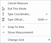
displayed to show this. Click the right hand mouse button to use the Measure
shortcuts menu:
Snap To Item will cause the picked start or end point to snap on to the closest part of the item selected. If a pad is being measured, the snap point will be at the pad’s centre.
You may use the Type Coordinate dialog from this menu to select an exact position to measure from by typing the required coordinates, or to choose a item by typing a component or pad name. For example, “U1” or “U1.8”.
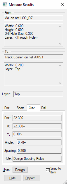
Use Show Measurement to toggle the display of the Measure Results dialog. This provides more information about the items being measured and is designed to be placed to the left or right of the screen. If you do not want the dialog in the way then hide it as the basic distance information is still displayed on the status bar.
-
If a single item was pre-selected, it will be used as the item to measure from. If nothing was selected, you will be prompted to choose the item or position from which to start measuring.
With Snap To Item on, single click to pick the first item, or click in space to specify a gridded position to measure from. Use the shift key to select a whole dimension, component or shape.
The selected item will be drawn in the select colour. A measurement line will be drawn in the select colour from the picked point on the item, to the moving cursor. The length of this line is shown on the status bar. If an item was picked, its details will also be shown on this bar. If the Measure Results dialog is displayed, details of the picked item or position will be shown.
If the wrong item under the cursor was selected, use the Select Next option (press the ‘N’ key unless reassigned) to cycle through the items under the cursor until you reach the required one.
-
You will now enter the measurement phase of the operation. Single click on the item or position that you wish to measure to. The item will be selected and the measurement line will be shown terminated on that item. Again, use shift click to select whole items, and Select Next option to alter the item.
With both items picked the Measure Results dialog (if displayed) will be updated with the measurement item you ended on and various measurements between the items.

“From” and “To” controls
These show dimensional information about the picked Items, or positions. If there is more information than can be displayed, the vertical scroll bars are enabled to view all the data.
Layer
This is only available for PCB designs, Footprints and PCB Documentation symbols. It shows the layer that the Gap between the items is measured on. If the two items are on different layers, “Different” is shown. In this case the gap is still shown, but may not be that relevant. If a picked item contains different shapes on different layers, a pad with layer reassignments for example, you will be offered a drop down list of common layers between the items to choose from. When choosing a different layer, the measurement information tabs and the line displayed on the design will be updated to show the measurement on the chosen layer.
Use Spacing Shapes
If one of the items is a pad, via or mounting hole and its style has a Spacing Shape defined the Use Spacing Shapes checkbox will be shown. If checked, and the spacing shape is on the current layer being measured, the spacing shape will be used instead of the actual pad land shape. if this is the case, the pad information will also be changed to show the spacing shape size.
Measurement Information Pages
These pages show different measurements between the two items. Picking a measurement tab will change the information page and alter the measurement line displayed in the design. The different measurements are as follows:-
Distance - Shows the distance between the picked points, and the angle of the line between these points.
Shortest - Is only displayed after two items have been selected. It shows the shortest distance between the two items. Widths of lines are not considered for this measurement, use the Gap tab for edge to edge measurement. If a component is selected the shortest distance is measured to its placement area on the relevant layer.
Gap - Is only displayed after two items have been selected. It shows the smallest gap between the edges of the two selected items. If both items are electrical items, it shows the required Spacing (and the corresponding spacing rule) between these items. This spacing is set to zero if the two items are on the same net. If two components are selected the spacing is the minimal component spacing. This page can be used to check two items to see if they are in error. If the gap is less than the required spacing, it will be drawn in red. If the layer is “Different” then the gap is not relevant unless one of the items changes layer.
Drill - Is only displayed if one of the two selected items has a drill hole. The distance shown is from the edge of the drill hole on these items. If both items have drill holes, the spacing shown is the minimum spacing required between drill holes.
Angle - Is only displayed after two items with straight sides have been selected. It shows the minor angle between the edges of the two selected items.
Neck - Is only displayed after two pads, mounting holes or vias which are contained in the same piece of copper have been selected. It calculates the shortest cut through the copper which would split the connection between the two pads.
Snap To Item Check this box to enable picking of design items for measurement. Leave it unchecked to restrict picking to positions in the design.
Hide/Show Measurements Use this to hide the results dialog. Measurements can still be made and the distances are shown on the status bar. Right click to use the shortcut menu option Show Measurement to display the dialog again.
Report Use this to generate a report recording the information in the Measure Results dialog.
When you have finished viewing the measurement results either on the status bar or in the Measure Results dialog, select another item to start measuring from, or press the Escape key to reselect the item you are measuring to.
To finish using the Measure tool, keep pressing the Escape key, or use the Exit This Mode option on the shortcut menu, or press the close button at the top right corner of the Measure Results dialog.
Units
Use this dialog to change the units used to display the lengths shown in the dialog. The button shows the units currently being used, and will show “Design” if the design units are being used. When pressed the following dialog will be displayed:

Define Measure Units - Select this button to define your own units for the Measure Results dialog. Type into the Units Text field the text to be displayed after each measurement.
Use Design Units - Select this button to use the units defined in the current design being measured.
Show Dual Units When checked, extra controls become available to define the second unit of the measurement, which is in turn, displayed on the main Measure dialog.
Related Topics
Technology - Spacing Rules | Design Units | Insert Dimension | Select Mode