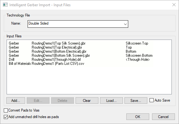
Intelligent Gerber Import allows you to intelligently rebuild a design from a set of Gerber, NC Drill, Bill of Materials files and Pick & Place files.
You may wish to use this option to rebuild older designs where you do not have the original design data or it was created in a PCB design package that cannot be imported to Pulsonix. If you have Gerber and NC Drill (and optionally a Bill of Materials), you can use these as the import file and rebuild the design. As a step on from this, you can also use the Reverse Engineer option to get the design back to a matching Pulsonix Schematic.
Shortcuts
Default Keys: None
Default Menu: File
Command: Intelligent Gerber Import
Locating this option
Available from: File menu > Intelligent Gerber Import option
Using the dialog

The Import Process
Regardless of whether you have a PCB design open or not, a new PCB design is created for you during the Intelligent Gerber Import process. This option is designed to create a new design and not append Gerber data to your existing design. If you wish to do this, use the Gerber Import option from the File menu.
The process for using this dialog is to select the required Gerber files. Depending on what you wish to be imported and rebuilt as a design will determine your file selection. Generally, you will choose a Top and Bottom Gerber layer, a drill file and optionally, a Parts list (BOM). You might also choose Silkscreen layers if available to help refine components for rebuild.
Once you have selected the data files, press OK to start the import process. Once the files have been imported you will have a design containing Free Pads connected by Tracks. The Tracks would have created during the import of the Gerber data from Gerber ‘lines’ intelligently connected together.
If a Bill of Materials (BOM) has been defined for import, the Component Bin will contain any Components that match the BOM Part name from your libraries. If your library does not have the Parts available, it will warn you that they are missing. It means that when you attempt to rebuild your design, you will either have to create new Parts and associated footprints, or generate them from the pads selected in the design.
If Components are in the Component Bin, then when Generate Component is used, you can choose one of the Component Bin components from a drop down list under Library Item - Part provided the number of footprint pads also matches the pads selected in the design. If not, use the Find In Library button to select the Component from the Library.
Similarly, if a Pick & Place CSV file has been defined for import, Intelligent Gerber Import will attempt to place components in the design using the data provided.
In order for this to work there must be matching parts in the libraries for those defined in the Pick & Place data. If there isn’t a match for a part then an empty part will be added to the Component Bin which can be used when generating components using the Generate Component dialog.
The design will have Free Pads which have been added during the Gerber import. Collectively, these represent a component when the appropriate pads a grouped together. Individually, they are just free pads in the design. To get these back into something that represents a Component, you can use the Generate Component tool. This will convert free pads and silkscreen shapes into components and symbols and the Free Pad to Via tool to create vias. Selection of free pads in the design will enable the group that represents a component will be chosen, then Generate Component used.
Dialog Navigation
Technology File
You should select an appropriate Technology File before adding any data files. The technology will define which layers are available to the importer.
Add - Adding data files to the list
On the first time of adding file to the list, it is quicker to use drag and drop of the required files from Windows Explorer onto this dialog. You can drag each file or a selection of legal files. Each one will be processed during opening in sequence.
The Add button can be used to add data files to the list of files to be imported. You still drag and drop individual files as well. Nothing is imported until the main OK button is pressed on the dialog.
You may choose one or more files of the available types (Gerber, NC Drill and BOM) to open. If you have all the required files in one location, multiple file selection will save you time.
Edit - Editing data files in the list
Use the Edit button on a selected file to edit its contents. This will present you with the relevant Settings dialog depending on whether you selected a Gerber file, NC Drill file or a Bill of Materials file.
Delete - Deleting data files from the list
Use the Delete button to remove selected data files from the list.
Clear
Use the Clear button to clear the complete list.
Load
Use the Load button to read a previously save import file list.
Save
Use the Save button to save the list of files and the settings used in each dialog to a file. This list can then be used on another import session. Use the Load button to recall the list.
Auto Save
By selecting this button, the current list will automatically be saved. When this option is next run, the list will be recalled.
Convert Pads To Vias
Use the Convert Pads To Vias option to convert all connected Free Pads to Vias. This is particularly useful if you have a pin limited version of the program, otherwise the imported design may exceed your limit as free pads are treated within the pad capacity.
Add unmatched drill holes as pads
With the Add unmatched drill holes as pads check box selected, the importer tries to match drill holes (in the drill file) with pads/flashes in the Gerber file. This enables data that has holes only but no pad, such as mounting holes, to be imported. If the drill does not match a pad, it adds a pad for the drill hole even when it does not match a pad in the Gerber, otherwise a pad will not be added (and so no hole).
Importing Gerber X2 data
If the Gerber file contains X2 format commands (AperFunction, FileFunction or Part), an additional message will be displayed on the dialog to inform you that these commands have been detected but will not currently be processed. For more information about Gerber X2 import restrictions click here
Pin Limits
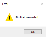
Something to be aware of - the pin limit of your PCB variant will affect the intelligent Gerber Import option. If the Gerber files being imported have more pads than your pin limit allows, the design will be rebuilt and drawn but then a warning message will be displayed informing you of this. Pressing the OK button will close the message and also close the design.

Intelligent Gerber Import Dialog
Gerber Import | NC Drill Import | Bill of Materials (BOM) Import | Pick & Place files
Related Topics
Generate Component | Free Pad to Via | PCB to SCM Reverse Engineer | Flat Gerber Import | Plotting Gerber