Use the Synchronise Designs tool from the Tools menu to compare and update the Schematic and PCB designs to ensure they are the same.
Fast Synchronise
You can also run Synchronise in Fast Synchronise mode. This is the same as the regular Synchronise Designs option except you can configure which parts of the process can be done without any additional interaction or input, and the option will run silently. The whole point of this mode is that it will ‘just do it’ for you (once your options have been set).
Switches to select the Synchronise options are available on the Options - Fast Synchronise page. Once enabled, you can add (from the Customise Commands page) the Fast Synchronise option to a toolbar or menu from where it can be run.
Shortcuts
Default Keys: None
Default Menu: Tools
Command: Synchronise Designs
Default Keys: None
Default Menu: None
Command: Fast Synchronise
Locating this option
Available from: Tools menu > Synchronise Designs option
Using Synchronise Designs
This option is available in both Schematics and PCB, and can compare and make changes in the corresponding design. You can use Synchronise Designs at any time to verify that the netlists are the same. If there are differences, a dialog will appear, allowing you to view a report and perform an update. The report will give you a list of changes which would have to be made to the PCB or Schematic in order to make them match. You can then perform these changes automatically by selecting the Update PCB or Update Schematic option.
First you will be presented with a dialog to choose which design you are comparing with. Normally you will want to compare the corresponding Schematic and PCB designs, but you can specify a different version of a design if you wish.

The recommended way of working is to create a schematic design, then use Translate to PCB to create the PCB design. The schematic design is considered the master and engineering changes should be made to the schematic, then passed forward to the PCB using Synchronise Designs.
Examples of engineering changes are adding or deleting component pins from nets, and adding or deleting components. Engineering changes can be destructive and performing an update on the PCB may result in tracks being removed. Large scale alterations to the netlist will result in large scale changes in the PCB.
Note that PCB Only Components and PCB Only pins on components are not part of the design comparison because there is no matching entity in the schematic. (See Parts Editor).
If you do want to make engineering changes in the PCB, you can treat the PCB design as the master and use Synchronise Designs to update the schematic. To do this use the following procedure:
- Synchronise the two designs to ensure they match, use the Tools menu and Synchronise Designs option.
- Take the PCB design out of Safe Mode by unchecking the PCB in Safe Mode box in the Design Settings - Synchronisation dialog.
- For the PCB design, enable Backward Design Changes by checking the Allow Update of Schematic to match PCB box, using the Design Settings - Synchronisation dialog.
- Put the Schematic design into safe mode by checking the Schematic in Safe Mode section in the Design Settings - Synchronisation dialog.
- Make the engineering changes to the PCB design and use the Synchronise Designs option to update the Schematic design with the change.
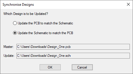
If the Allow Update of Schematic to match PCB setting is enabled, the following dialog will be the next stage in the Synchronise Designs procedure. Specify which way the changes are to be applied by selecting which design is to be updated. When you update the designs, the Safe Mode options will be adjusted if necessary, to reflect the direction of the update selected. So the design you choose to update should be the one in safe mode.

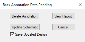
Annotation changes can be made in the PCB, and these can be passed back to the schematic using Back Annotate. Synchronise Designs will inform you of, and allow you to perform, any back annotations which are pending as the next stage in the Synchronise process. If there are annotation renames pending, the following dialog will be presented:

If you are updating the PCB, it is recommended that you back annotate the changes first, because the design compare it performs does not take any pending back annotation into account.
If you are using synchronise to update the schematic design, the Back Annotation dialog allows you to make these changes to the schematic first. You may want to do this because changes such as gate swaps are more efficiently applied to the schematic this way. Otherwise, the general compare and update phase will make equivalent netlist changes.
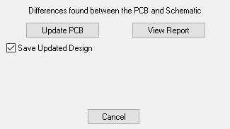
Next the two designs will be compared and if they are not the same you will be presented with the following dialog:

Note, if you are using the PCB design as the master, the update button will show as Update Schematic.
If new components are to be added to the target design, you will be presented with the option to add these components to the bin (and display the bin if necessary). Otherwise, new components are placed around the board outline.
If updating a schematic design, the new components are always added to the bin. The gates of a new component will be added to the relevant unused or used section of the schematic bin, but if the component is completely unconnected one gate is always added to the used section to indicate a new component has been added.
You will be presented with the option to Keep Tracks if components have been removed, or component pads have been disconnected or changed nets. Keep Connections to these components as dangling lines. Select the sub-option Remove connected segments to keep the existing tracks but the connected segment.
A check box allows you to choose to Save the Updated Design.
Press the Update button to perform the changes to the target design to make the designs the same. At the end of the updating phase, you will be asked to save the design that has been updated. If updating the schematic design you may be asked to save the PCB as well, because it might have new internal IDs allocated for its components and nets. These IDs help future Synchronise Design operations by associating corresponding PCB and Schematic items.
It is possible to define design spacing rules and to define specific footprints on components in the schematic design. These can be synchronised with the PCB design, see Design Settings - Synchronisation for more information.
You should consider using the PCB SAFE MODE option in Design Settings - Synchronisation. This will prevent you from making engineering changes in the PCB, which should be made in the schematic design and passed forward using the method described above.
Updating the Schematic Design
If you have made the decision to make engineering changes to the PCB design, you should consider using the Schematics Safe Mode option in Design Settings - Synchronisation. Checking the Schematics in Safe Mode box will prevent you from making engineering and annotation changes in the Schematic, which should be made in the PCB design and passed back using the method described above.
Some changes may not be able to be made to the schematic design, for example when the change is in a multiply instanced block, or the block has its contents locked. You will be warned if changes could not be made and will have to either change the PCB design a different way, or change the schematic design so that the updates can be made.
If the schematic contains a component that represents a range of components by using the range format in its name, any change in the PCB of one of the components in the range to be different from the rest will cause all of the components in the range to be separately instanced in the schematic design.
Synchronise In Multi-Screen Mode
When you are working in multi-screen mode, Synchronise Designs has to work across the two instances so that information about the Schematic and PCB are shared between the two. Depending on which changes need to be applied, and the direction in which you choose to apply them, Synchronise may display its various dialogs in one or other screen, or sometimes both.
Consider for example the situation where you have a Schematic and PCB design ‘pair’ open, the PCB design has Back Annotation changes waiting to be applied to the Schematic, and you have also connected a new component into the Schematic so those changes need to be applied to the PCB. If you invoke Synchronise Designs from the Schematic instance, it will detect the fact that the chosen PCB design is already open in the other instance. If the PCB has been modified, you will be prompted to save the changed PCB design to disk so the Schematic instance can read it. The back annotation data from the PCB design file will then be applied to the Schematic in the Schematic instance. At the same time a copy of the same Schematic design will be used in the PCB instance to carry out the ‘normal’ Synchronise sequence of Back Annotation followed by Forward Design Changes. The designs in both instances will thus be Synchronised by applying the appropriate set of changes in each instance.
To run Synchronise in Multi-Screen mode, you can choose Synchronise from either Schematic or PCB as usual. Depending on whether changes have been made to your designs since they were last saved, you may be prompted to save modified designs so the up-to-date copy can be read in the other instance. For the duration of the Synchronise operation, the design in the ‘other’ instance may be placed in ‘read only’ mode so that the controlling instance can access the design data, so you may notice the window caption changing to say ‘View Only’ and a number of the toolbar and menu options becoming greyed out. The design will be returned to its normal state on exit from Synchronise.
Related Topics
Translate to PCB | Back Annotate | Design Settings - Synchronisation | Options - Fast Synchronise | Parts Editor