The waveform generator component is used to create a time domain signal for transient analysis.
Use this dialog when editing a Part to define the Part as a Waveform Generator.
Use it on a Waveform Generator or Current Waveform Generator component in a schematic design to specify the values for the source.
These parts have their Spice Type Built-in Function set to Source - Waveform Generator or Source - Current Waveform Generator.
Shortcuts
Default Keys: F7
Default Menu: Simulation
Command: Edit Spice Value/Model
How To Add A DC Source Component
Once you have a circuit that you wish to simulate, add a Waveform Generator device to provide a stimulus for the circuit. There are various ways to add a Waveform Generator to a Schematic Design:
- From the Parts toolbar, click on the Sources pop-up (battery symbol) to display the Sources toolbar. Click on the Waveform Generator or Current Waveform Generator buttons.
- From the Parts Browser, click on the Sources category to display a list of sources. Drag the any of the part names mentioned in method 1 above, into the design. Note: This method may not work if you have changed the part categories.
- Use Component from the Insert menu to add Parts with the names mentioned above in method 1, from the SPICE library.
Whichever method is used, you should be presented with a Voltage or Current Waveform Generator to place in the design.
How To Define A Waveform Generator
In a Schematic Design, select the Waveform Generator device(s) that you wish to change. Press F7 or use the Edit Spice Value/Model option from the Simulation menu, or from the shortcut menu.
From a Parts Library edit the required Part. Press the Edit Spice button on the Details tab. Make sure the Built-in Function is set to Source - Waveform Generator or **Source
-
Current Waveform Generator** and press the Edit Value button.
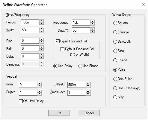
In both cases the following dialog will be displayed:

Select the Wave Shape on the right hand side then enter the parameters as appropriate. The following notes provide details on some of the controls.
-
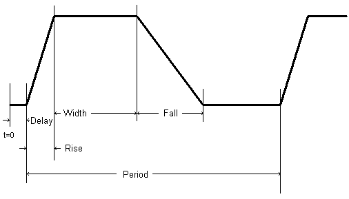
The diagram below defines the waveform timings for a Pulse shape:

Frequency = 1 / Period
Duty = (Width + Rise/2 + Fall/2) / Period
-
Damping describes an exponential decay factor for sine wave shapes. The decay is governed by the expression:
e-damping*t
-
Off Until Delay if checked specifies that the signal will be at the Initial value until the delay period has elapsed.
-
Note that some parameters can be specified in more than one way. For example both Frequency and Period edit controls are supplied. Changing one will cause the other to be updated appropriately. The same applies to Duty and Width and the vertical controls in the lower half of the dialog. The Vertical aspect of the signal can be specified using Initial Value and Pulsed Value, or by using the Offset and Amplitude of the signal.
-
If Rise or Fall are set to zero or negative, then they will use the Time Step, which is a the first parameter of the .tran Transient Analysis simulator control.
-
If a Step pulse is used, the pulse Width will be equal to the Stop Time squared. The Stop Time refers to the end time of the Transient Analysis.
-
If a One Pulse is used, the Period will be equal to the Stop Time.
-
Pulsonix-Spice deviates from standard SPICE in the action taken for a pulse width of zero. Standard SPICE treats a zero pulse width as if it had been omitted and changes it to the stop time. In Pulsonix-Spice a zero pulse width means just that.
Editing Multiple Components
If any of the fields are set to
Related Topics
AC Source | DC Source | Edit Device Type | PWL Source | Universal Source