Use this to create a subcircuit netlist file from a schematic circuit.
Shortcuts
Default Keys: None
Default Menu: Simulation
Command: Create Netlist As Subcircuit
Subcircuits
Subcircuits are a method of defining a circuit block which can be referenced any number of times by a single netlist line or schematic device. Subcircuits are the method used to define many device models such as op-amps. You do not need to know anything about subcircuits unless you wish to define you own device models, perhaps to build up a library of tested blocks for general distribution. This section explains how to create a subcircuit from a schematic.
How To Create A SPICE Subcircuit
Subcircuits must be defined in text form as a netlist. However the schematic editor can be used to generate the netlist. To create a sub-circuit from a schematic, you need to identify which nodes are to be connected externally. This is done using Subcircuit Pin components. These are special parts that have their Spice Function set to Subcircuit Pin.
The procedure for defining a subcircuit is as follows:
- Draw circuit using schematic editor including Subcircuit Pin parts to identify external connections.
- Create netlist for subcircuit.
Stage 1 - Draw The Schematic
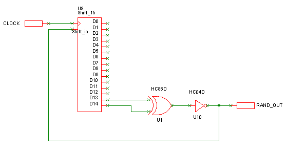
To describe the procedure, we will use an example.

The two single pin terminal components are the connections to the outside world. These are Subcircuit Pin components which can be added using one of the following methods:
- From the Parts toolbar, click on the Miscellaneous pop-up to display the Miscellaneous toolbar. Click on the Subcircuit Pin button.
- From the Parts Browser, click on the Miscellaneous category to display the Miscellaneous parts. Drag the Subcircuit Pin part name into the design. Note: This method may not work if you have changed the part categories.
- Use Component from the Insert menu to add the Part called Subcircuit Pin from the SPICE library.
Use F7 on these components to enter their subcircuit pin names. If the name is left blank the name of the net connected to the component will be used.
It is recommended that any model definitions are included in the subcircuit definition. This makes the subcircuit self-contained. If you have referenced models in the device library, you can import them into the schematic automatically using the Import Models button on the Extra Simulation Data dialog, accessed from the Simulation menu.
Stage 2 - Create The Subcircuit Netlist
Use the As Subcircuit option from the Create SPICE Netlist File sub-menu on the Simulation menu.
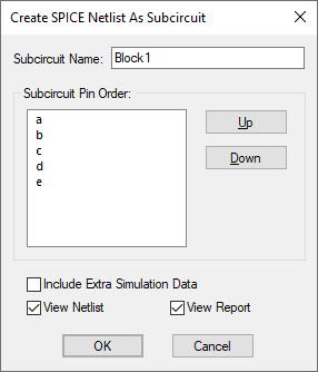
The following dialog will be displayed:

Fill in the dialog and press OK to create the netlist for the subcircuit.
Subcircuit Name
Enter the name of the subcircuit. This name will also be used for the netlist filename with extension “.MOD”. The default displayed is the name of the current page of the circuit.
Subcircuit Pin Order
This is a list of the Subcircuit Pin components representing the external pins on the subcircuit. Press Up and Down to correctly order these pins.
Include Extra Simulation Data
Check this box to include any extra SPICE data you need in the subcircuit’s netlist. For example to include the model definitions (see above).
View Netlist
Check this box to view the resultant netlist file.
View Report
Check this box to view a report showing the selected pin order and detailing any warnings or errors found whilst creating the netlist.
Unsuitable Circuits
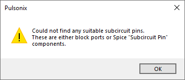
If the circuit does not contain any Subcircuit Pin components the following error message will be given and the dialog will not be offered.

Related Topics
Define Subcircuit Pin Name | Define Spice Type | Extra Simulation Data