PCB Tracks are the physical copper paths between component pads. These copper paths not only lie on an electrical layer but can also push through to another electrical layer using a Via. A Via is a plated through hole used as a through hole connection between the layers on the circuit board. Tracks can be attached to these vias on any of the electrical layers through the board. Vias can also be placed within a copper area to take the signal to another layer.
Shortcuts
Default Keys: V
Default Menu: Insert
Command: Insert Via
Locating this option
Available from: Insert menu > Via option
Vias Explained
The physical appearance of the via is defined using a Pad Style. This defines the pad shape, size and drill hole size, and you can reassign the via size on any layer. The colour, selectability and visibility of vias is defined on the Colours dialog.
Vias are always on a net and when inserted they get their Pad Style, from the Net Class the net is on. If the via style is not defined for the net class, the via takes its style from the Via default dialog.
Vias can be protected against being altered by a change of track layer by switching off the Allow Automatic Changes settings in the Properties dialog. A via that is not protected only exists to complete a copper path between two tracks on different layers. As soon as it is no longer needed for this function it is automatically removed. Protected vias are not automatically removed and exist to connect a single track, copper shape or power plane, to a copper shape or power plane on another layer. Protected vias do not need tracks attached to connect layers.
In a Footprint a Component Via is inserted. These are different to normal vias and are intended to represent vias which are fixed within a component. They do not have to be on a net and have special properties to allow them to be excluded from normal rule checking. If you want to add a component via to the same net as a pad after inserting it, select both the via and the pad and use the Add To Net option from the shortcut menu. Type the pad number as the net name. This will force the via to always be on the same net as the pad when the component using this footprint is added to a PCB design.
Using The Insert Via Option
-
Enter the Insert Via option by using Via from the Insert menu. A via will appear, attached to the cursor.
-
Move the mouse to position the via. If placing a single via and Show Finish Markers is enabled, a “V” cursor will be displayed if the via is over an item the via can attach to.
-
Right click to use the shortcut menu to change the via. Some options available are as follows:
Use Type coordinate to place the via at a known position.
Use Insert Multiple Items to switch from adding a single via to adding multiple vias at the same time. A dialog will be displayed for you to specify how many vias in each direction and the gap between them. Note, you can use the shift key whilst selecting the Add Via option to automatically enter the Insert Multiple Items dialog straight away.
Use Change Layer Span if you are using blind and buried via technology and wish to change the span of the via through the board. You will be presented with the Change Layer Span dialog to alter the span of the via.
Click on Change Style to use the Change Pad Style dialog to alter the appearance of the via.
If adding vias to a PCB design, use Change Net to add the via to a new or existing named net using the Change Net Dialog. The via, or multiple vias, being added will be moved from their current net to the new net.
If adding vias to a PCB design, use Change Testpoint to make the via a named testpoint. Type the required name using the Change Testpoint Dialog.
Switch on Display Clearance to highlight potential obstacles whilst placing the via.
Switch on Online DRC to enable design rule checking against obstacles as the via is placed.
Use Change Grid - To change the grid step used for placing vias.
-
Click to drop the via or vias in the required location. If you are adding a single via to a PCB design and it is dropped over an electrical item on a net, it will be added to that net. If you drop a single via on a track, it will be inserted into the track.
Another via will automatically appear on the cursor ready for placement.
-
When you have added as many vias as you require, use the Esc key or Cancel from the shortcut menu to abort adding the current via being placed. This will exit the Insert Via mode.
Adding Vias Automatically
- During Insert Track you may end the track on a via. In Insert Track mode right click the mouse, select End Track On then Via. A double click will terminate the track on a via
- During Insert Track you may insert a via automatically by changing layers. In Insert Track mode right click: mouse select Change Layer. A via will be inserted at the last segment point through to the selected layer
Changing The Via:
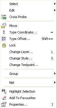
Select or select Edit the Via, right click the mouse, the shortcut menu opens:

You may:
reposition the Via using Move
change the Via Pad shape using Change Style
change the Via layer using Change Layer
Related Topics
Insert Multiple Items | Change Layer Span | Change Net | Change Via Style | Technology | Via Defaults | Properties - Component Via | Design Rule Checking | Grids