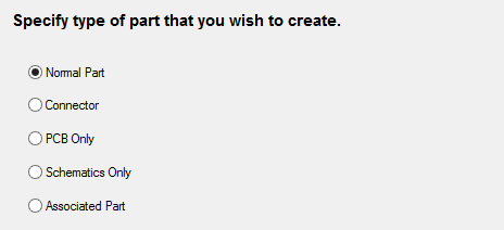
This page allows you to choose the type of part to be created by the Wizard.
How to Use This Page
Select the required type. The step list on the left side of the dialog will change to be more relevant to the type of part chosen.

Normal Part
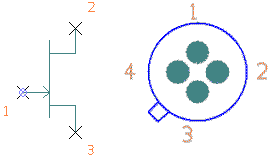
Choose “Normal Part” to create a part that will appear on a Schematic drawing as one or more “gates” and on the PCB design as a footprint. Most parts you create will be in this category. This includes parts that only use one Schematic symbol, as well as those that have multiple symbols (“gates”).

Connector
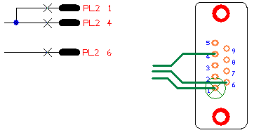
Choose “Connector” to create a part that represents a plug, socket or other kind of connector. The difference between this type of part and a “Normal” part is that you only have to define the Schematic symbol for one pin of the connector. This saves you having to create all the gates that would otherwise be needed.
Each pin of the connector can be added individually to the Schematic drawing as they are required. These are then combined when the PCB design is created from the Schematic.

PCB Only
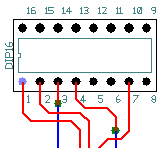
Sometimes you may need a part for which you do not have a Schematic symbol, or you only need to create the PCB design and hence are not concerned with the Schematic representation. Select “PCB Only” to create such a part. The diagram below shows part of a PCB design where a “generic” (PCB only) part has been used.

Schematics Only
Sometimes you may need a part that is only used in the schematic, and hence are not concerned with a PCB representation. These are usually used for Spice control devices, like sources and probes, and are only needed for simulation. Select “Schematics Only” to create such a part.
Associated Part
Use this to create mechanical parts that are associated with normal parts. Associated Parts do not physically appear in the schematic or PCB designs, but do appear in the parts list. These are useful for adding screws, heat sinks , sockets, etc., which must always be present when a part is used in a design. Select “Associated Part” to create such a part.
Part Wizard Pages
Start | Part Details | PCB Footprints | Power and Ground Pins | Schematic Symbols | Gate Pins Details | Attributes | Finish