Bias Voltage and Current Markers are components used to annotate the schematic with the results of a DC Operating Point analysis, displaying the voltage on the net, or current on the pin, they are placed on. The values shown on the markers are updated each time you simulate.
Shortcuts
Default Keys: None
Default Menu: Simulation
Command: Insert Bias Marker
Using Bias Markers
Bias Marker components should have a single pin. The voltage marker component should have the component Spice function set to Bias Voltage Marker, and the current marker component should have the Spice function set to Bias Current Marker. Both should also have the Spice value set to zero, ready for receiving and displaying the analysis result. There are special components “Bias Voltage Marker” and “Bias Current Marker” provided in library Spice parts library.
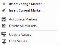
Several options exist to make it easy for you add, delete, hide values and update values on bias markers. These functions are found on the Bias Annotation sub menu from the main Simulation menu as follows:

Individual bias markers can be added using the Insert Bias Marker and Insert Current Marker options from the Bias Annotation menu, or from the simulation toolbar.
Bias Voltage Markers should have their pin attached to the net you wish to display the value for, and Bias Current Markers should have a connection from their pin to the device pin you wish to display the value for.
Use the Autoplace Markers option from the Bias Annotation menu to automatically add a voltage marker component to each net in the schematic design.
First all existing Markers on the Schematic Page will be removed. Then a Bias Marker will be added to all nets on the page.
If you have already run a simulation, you may now update the values displayed on the markers by using the Update Values option.
Use the Delete All Markers option from the Bias Annotation menu to automatically remove all Bias Voltage Markers from the current page of Schematic design.
Use the Hide Values option from the Bias Annotation menu to automatically hide the values on all Bias Markers. You may hide and restore values individually by selecting markers and using the Attributes tab in the properties dialog.
The values displayed on all the markers can be restored using the Update Values option. It automatically updates each bias voltage marker in the current schematic design from the results of the latest DC Operating Point analysis. The bias marker components should be updated automatically after each simulation run, but you may need this option to show the voltage values if they were previously hidden, or if the format has been changed.
The format of the marker values can be changed using the Bias Annotation Format section in the Simulation Options dialog.
Related Topics
Autoplace Markers | Delete All Markers | Hide Values | Insert Bias Marker | Simulation Parameters | Update Values